


RM6
- The Leader in DJ Technology
©1999 Industries - 5 - http://www.numark.com
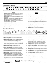
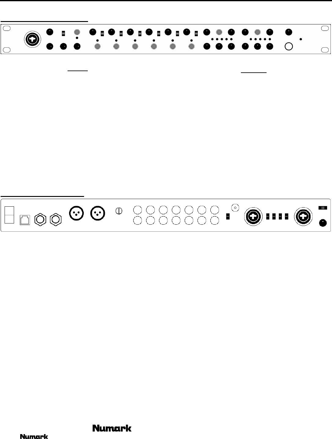
Front Panel Features
1
2
3
4
5
6
7 8 9
10
11
12
13
INPUTS
1. Input gain knobs - control individual source levels in the mix.
Note to contractors: After setting final input level, remove the
knob to avoid tampering.
2. On/Off switches – allow sound to be brought into the unit on
each channel.
3. Zone Assign – determines which zone the audio is directed to.
The middle position sends channel audio to both zones
4. Mic Gain Control – controls the mic volume for the Neutrik™
“Combo” connector on the front panel.
5. Mic Gain Control – adjusts the Treble, Middle, and Bass
frequencies respectively of the mic audio.
6. Neutrik™ “Combo” connector - allows connection of either a
1/4” jack or an XLR jack. This is ideal for connecting an XLR
gooseneck directly into the mixer.
OUTPUTS
7. Zone Fader – controls the overall output level.
8. Mono/Stereo – sets this mode for the output audio.
9. Panning – controls the mix of stereo audio available from the
channel. When moved to the left only the left speakers will be
heard, or to the right for the right speakers.
10. Stereo Level Indicator- quickly and accurately tracks level of
audio output. When using as a master output meter, set the
crossover, equalizer and power amp inputs to avoid distortion at
each step in the audio chain. Proper attention to the peak meter
results in the punchiest possible sound without audible
distortion.
11. Zone EQ – adjusts the Treble, Middle, and Bass frequencies
respectively of the zone audio.
12. Headphone Level – adjusts headphone volume.
13. Headphone Jack – for plugging in your headphones.
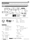
Rear Panel Features
14
15
16
17 18
19 20
21
22
23 24
25 26
27
28
14. Power Switch – to turn unit on.
15. Power Supply Input - to plug your power adapter in before
switching on power.
16. Balanced Zone 2 Outputs - are 1/4" Stereo Balanced TRS 1/4”
connectors controlled by the Zone 2 fader knob. Power
transformers and other devices that cause magnetic fields can
induce hum in audio cables. This can be best resolved by using
balanced lines where inputs and outputs permit. Balanced lines
are also the most effective means of reducing or eliminating RF
or radio frequency" interference.
17. Balanced Zone 1 Outputs - are Balanced Stereo XLR
connectors controlled by the Zone 1 fader knob.
18. Master Gain Reduction – to set optimal output level of the
balanced outputs to be set at .245V to 2.5V to match the optimal
inputs of amplifiers and other devices.
19. Unbalanced Zone Outputs –output controlled by the Zone
fader knobs.
20. Record Output – collective of output sent to either zone.
21. Unbalanced Line Inputs - to connect stereo audio from HiFi
VCRs, cassette and reel-to-reel tape decks, DAT machines, CD
players, laser discs, tuners, even synthesizers or other mixing
consoles.
Note: Plug mono audio sources into both Left and Right inputs
using a “Y" cable connector.
Note: Line 3 can receive a turntable input depending phono/line
switch position.
22. Phono/Line switch – select the appropriate position for your
input device. With phono selected the input signal is fed
directly to the high-quality RIAA phono pre-amplifiers so use
this input only for turntables. Line level sources will overload
the sensitive phono pre-amps. Switch this over to the Line
position for line devices such as CD players and Tape decks.
23. Ground lug - use these connections with your turntables’
grounding cable to avoid signal hum.
24. Neutrik™ “Combo” connector - allows connection of either a
1/4” jack or an XLR jack to connect balanced line or mic inputs
depending upon switch position.
25. Mic/Line switch – to allow inputs of either balanced line input
or microphone into the referenced XLR jacks.
26. Stereo/Mono Switch - allows the user to adjust the signal input
for stereo or mono input accordingly.
27. Auto-Talkover Control – sets the front panel mic to
automatically reduce other source level when the mic is spoken
into. Positions are available for either off, -12dB, and – 40dB
(complete reduction)
28. Talkover sensitivity adjust – determines the point in which
auto-talkover activates. The more sensitive the adjustment, the
quieter you need to speak into your microphone to activate auto-
talkover.