


SPECIFICATIONS PM
™
18S
A
A
R
R
C
C
H
H
I
I
T
T
E
E
C
C
T
T
U
U
R
R
A
A
L
L
&
&
E
E
N
N
G
G
I
I
N
N
E
E
E
E
R
R
I
I
N
N
G
G
S
S
P
P
E
E
C
C
I
I
F
F
I
I
C
C
A
A
T
T
I
I
O
O
N
N
S
S
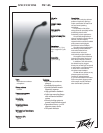
The microphone shall be back-
electret, condenser type with
a
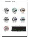
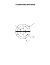
frequency response of 50 Hz to 20
kHz. The microphone shall have
a
cardioid response pattern with a rear
response that is typically -20 dB from
the front response. The microphone
shall have an output level of -39
dBV/pascal with a nominal impedance
of 250 Ohms. The microphone shall
have a low-gloss finish. Microphone
dimensions shall be 0.5" (12.5 mm) i
n
diameter at the element and 18.1"
(460 mm) long. The output shall
properly interface the microphone
with any
9 to 52 Volt phantom power
supply.
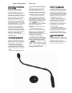
Dual, flexible tubing shall be
incorporated in the neck assembly to
allow proper positioning of the
microphone. The microphone shall be
a
Peavey PM 18S.
C
C
O
O
L
L
L
L
E
E
T
T
M
M
O
O
U
U
N
N
T
T
I
I
N
N
S
S
T
T
A
A
L
L
L
L
A
A
T
T
I
I
O
O
N
N
Remove template from carton.
Position
the template at the desired
position on
the lectern. Placing it near
the upper right or left corner of the
reading surface is most practical.
Use
tape to hold the template in
place while you mark
the location of
center clearance and (3) mounting hole
centers.
Remove the template and drill a 1"
(25.4 mm) center clearance hole. Next
,
drill (3) 3/32" (2.38 mm) screw
pilot
holes.
After making sure the 1 1/2"
(38.1 mm) suspension foam washer is
in the base of the collet mount,
attach
the collet mount to the lectern using
the three mounting screws provided.
Insert the connector end of the
microphone into the
top of the collet
mount and gently press down to the
desired depth. The connector end must
penetrate
the lower suspension foam
washer.
C
C
A
A
U
U
T
T
I
I
O
O
N
N
: Do not allow the
output module cap to rest on
the collet
collar top.
If this happens, the
mechanical isolation system becomes
ineffective.
Turn collet collar clockwise to
tighten or counterclockwise to loosen
the tension on the suspension system
.
Optimal tension is only enough to
prevent the
microphone from slipping
downward on its own
weight.
Holding
the top portion of the
microphone to prevent it from moving
up, connect the microphone
cable firmly
into the microphone output module.
C
C
A
A
U
U
T
T
I
I
O
O
N
N
: To preserve maximum
vibration
isolation, neither the output
module nor the
security clamp should
come in contact with the collet or th
e
mounting surface of the
lectern.
S
S
E
E
C
C
U
U
R
R
I
I
T
T
Y
Y
L
L
O
O
C
C
K
K
P
P
R
R
O
O
V
V
I
I
S
S
I
I
O
O
N
N
After the installation of the
microphone, simply slip the security
clamp around the microphone cabl
e
and position around the end of the
output module beneath the mounting
surface. Engage the jaws of the clamp
and tighten securely by squeezin
g
with your fingers or pliers.
While the clamp is in place, the
microphone cannot be removed. Thi
s
prevents theft and protects the
mechanical isolation system from
damage likely to occur if the XLR on
the microphone cable is pulled
through the collet.
To remove the microphone,
disconnect the microphone cable from
the output module and remove the
security clamp by sliding one ja
w
downward until the teeth disengage.
2
2
Y
Y
E
E
A
A
R
R
L
L
I
I
M
M
I
I
T
T
E
E
D
D
W
W
A
A
R
R
R
R
A
A
N
N
T
T
Y
Y
N
N
O
O
T
T
E
E
:
:
For details, refer to the
warranty statement. For copies of thi
s
statement, contact
Peavey Electronics
Corporation, at P.O Box 2898,
Meridian, Mississippi 39301-2898, or
go online to www.peavey.com.
2