


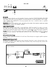
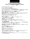

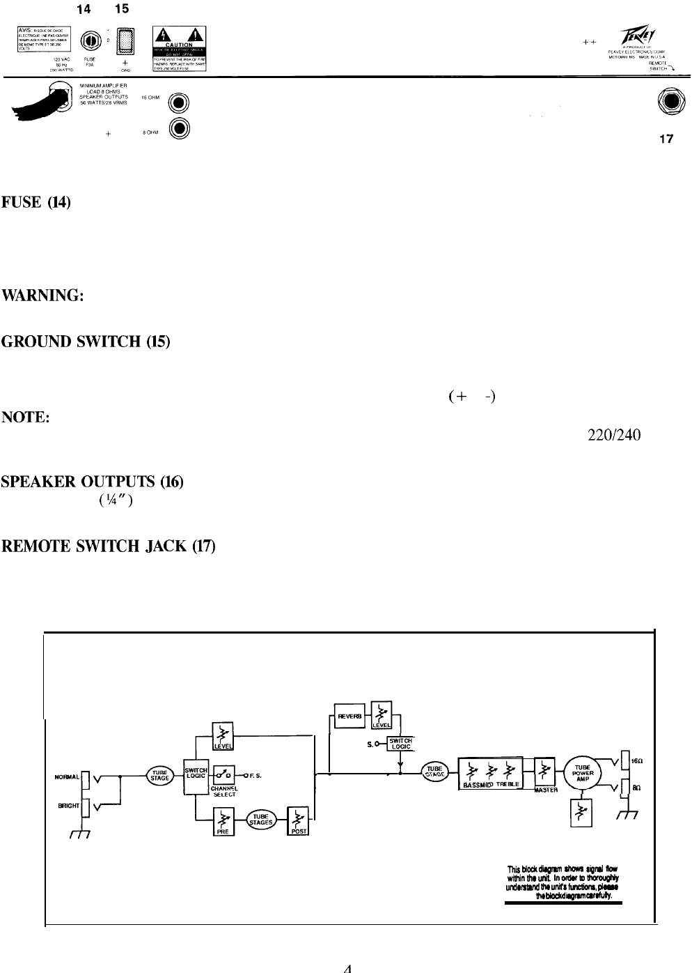
REAR PANEL
16
FUSE
(14)
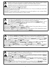
The fuse is located within the cap of the fuseholder. If the fuse should fail, IT MUST BE REPLACED WITH
THE SAME TYPE AND VALUE IN ORDER TO AVOID DAMAGE TO THE EQUIPMENT AND TO PRE-
VENT VOIDING THE WARRANTY. If the amp repeatedly blows fuses, it should be taken to a qualified
service center for repair.
WARNING:
THE FUSE SHOULD ONLY BE REPLACED WHEN THE POWER CORD HAS BEEN
DISCONNECTED FROM ITS POWER SOURCE.
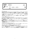
GROUND
SWITCH
(15)
Three position rocker-type switch which, in most applications, should be operated in its center or zero posi-
tion. There may be some situations when audible hum and/or noise will come from the loudspeaker. If this
situation arises, position the ground switch to either positive or negative
(
+ or
-)
or until the noise is minimized.
NOTE:
Should the noise problem continue, consult your Authorized Peavey Dealer, the Peavey Factory, or
a qualified service technician. THE GROUND SWITCH IS NOT FUNCTIONAL ON 220/240 VOLT
MODELS.
SPEAKER
OUTPUTS
(16)
Speaker output
(%
“) jacks are provided for 16 and 8 ohms. When both jacks are engaged, amplifier impedance
is 8 ohms.
REMOTE
SWITCH
JACK
(17)
Provided for the connection of the optional remote footswitch. Footswitch is used to select the Lead or Nor-
mal channels and defeat reverb. When using remote footswitch, always insert the plug fully (second click)
to ensure proper operation.
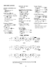
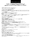
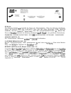
BLOCK DIAGRAM
INPUTS
NOFWAL
I
F. S.
f
so
BASS
,“I0
TREBLE
Ex2
El
J7
PRESENCE
lhii
blockd~r4m
3Kms
signd
nw
wtlhinthrunit
Inofdutottwoughly
undowand
the
unlh
fwdorm,
pIme
study
TV
bbck dbgmm
cafofuhrlly.
A