PILOT LED
(12)
This light emitting diode (LED) indicates when the amp is switched on and actually drawing from the line (mains)
connection. It is totally solid-state and not subject to burnouts, as are incandescent types.
POLARITY SWITCH (13)
This switch is a three position type with the center, zero position, completely removing the internal grounding capacitor
from the circuit. This position is normally recommended for situations where the AC power receptacle is known to contain
a properly grounded third wire. If properly grounded AC main supply is not available, a suitable ground adaptor should be
used. The (plus and minus) positions are used to ground the amplifier properly when only two wire services are available.
One of these positions will yield the lowest amount of residual hum or popping when the instrument is
touched.(NO-
TE:
Polarity Switch is not operative on export models.)
ON/OFF SWITCH
(14)
The On/Off Switch is a simple, two position rocker type, and should present no operational difficulties.
15 16
REAR PANEL
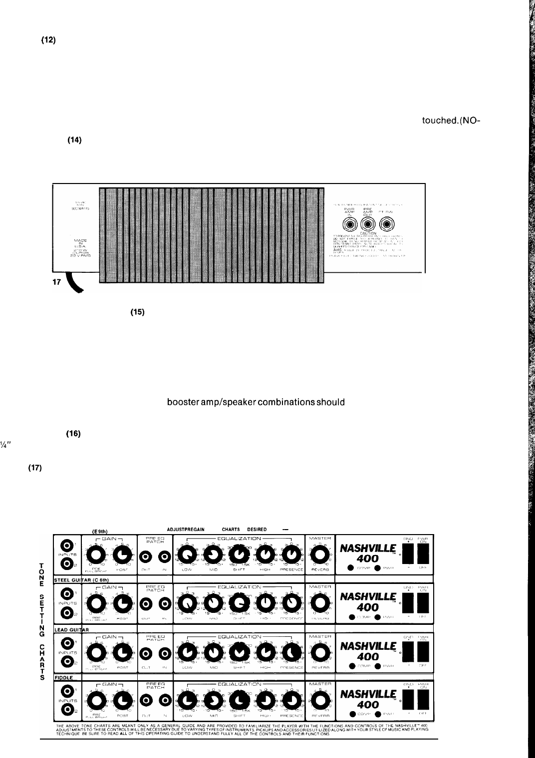
PREAMP OUT AND POWER AMP IN
(15)
To allow “in line” patching of various accessories we have included a system of preamp out/power amp in jacks on the rear panel.
The Preamp Out is a straight preamp signal which includes the entire equalization circuit plus reverb. The output level is
approximately 1 volt RMS and is relatively low, 600 ohms impedance. The Preamp Out signal is connected through a switching
contact to the Power Amp Input Jack and normally the preamp out is internally connected to the power amp’s input. This circuit
allows basically two modes of operation. When signal is taken from the preamp output, the signal is also delivered to the internal
power amplifier. If access to the power amplifier input is needed, or if some accessory device, such as a noise gate, delay line,
effects device, etc., is to be patched in line, then the preamp output signal must be connected to the auxiliary unit’s input while the
auxiliary unit’s output must be connected to the power amp input with shielded cables, thereby placing the auxiliary unit in series
or in line with the normal signal path. Additional
boosteramp/speakercombinationsshould
be patched using the preamp output.
With this unique patching facility many interested effects can be accomplished. Line level devices should be used with the preamp
out and power amp input.
FOOTSWITCH JACK (‘6)
The
5’4”
footswitch jack allows remote switching of the reverb system from the footswitch. The footswitch is a simple, single
function unit that merely defeats or cancels the internal reverberation capability.
LINE CORD
(17)
For your safety we have incorporated a three wire line (mains) cable with proper grounding facilities. It is not advisable to remove
the ground pin under any circumstances. If it is necessary to use the amp without proper grounding receptacles, a suitable
grounding adaptor should be used. Much less noise and the probability of shock hazard is greatly reduced when the unit is
operated with the proper grounded receptacles.
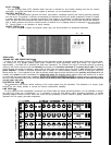
STEEL GUITAR
(E
91h)
ADJUST
PRE
GA,N ON ALL CHARTS TO DESlRED LEVEL
-
ADJUST MASTER REVERB ON ALL CHARTS TO PERSONAL TASTE


