


10
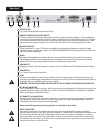
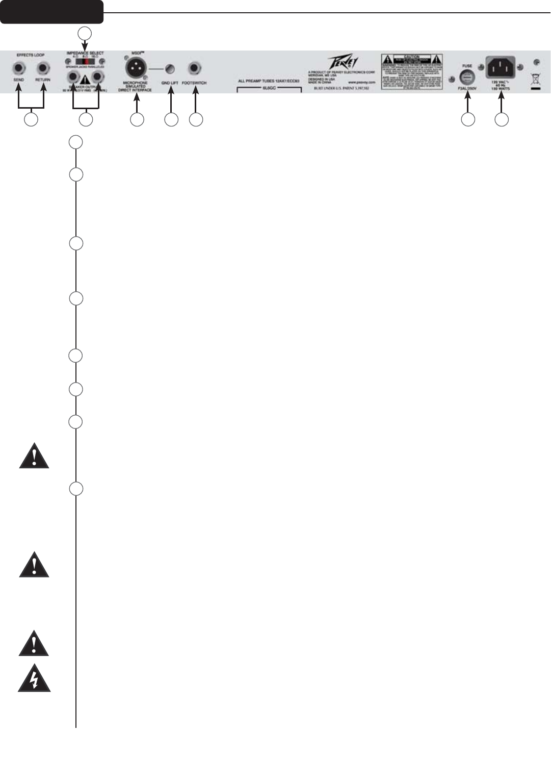
EFFECTS LOOP
1/4" Send and Return jacks for the effects loop.
CABINET IMPEDANCE SELECTOR SWITCH
This three-position switch allows appropriate selection of speaker cabinet impedance. If two loudspeaker
enclosures of equal impedance are used, the switch should be set to half the individual value. For example,
two 16-ohm enclosures necessitate an 8-ohm setting, while two 8-ohm enclosures would require a 4-ohm
setting. Minimum speaker impedance is 4 ohms. The stock setting for the internal speaker is 16 ohms.
SPEAKER OUTPUTS
These paralleled 1/4" mono (TS) jacks are provided for the connection of speaker enclosure(s). Again,
minimum speaker impedance is 4 ohms. The CABINET IMPEDANCE SWITCH (24) should be set to match the
load of the speaker cabinet(s).
MSDI
™
Microphone Simulated Direct Interface. Peavey's exclusive MSDI simulates teh sound of a microphone
placed approximately 8" from loudspeaker cone, allowing the user to send a clean signal to the mixing
console. This is a non-powered output and safe for use with any mixing console.
GROUND LIFT
Engage this switch if the mix engineer is hearing a hum in the MSDI output This should eliminate the hum.
FOOTSWITCH
1/4" input for the optional footswitch.
FUSE
A fuse is located within the cap of the fuse holder. This fuse must be replaced with one of the same type
and value to avoid damaging the amplier and voiding the warranty. If the amp repeatedly blows the fuse, it
should be taken to a qualied service center for repair.
WARNING: THE FUSE SHOULD ONLY BE REPLACED AFTER THE POWER CORD HAS BEEN DISCONNECTED.
IEC MAINS CONNECTOR
This is a standard IEC power connector. An AC mains cord having the appropriate AC plug and ratings for the
intended operating voltage is included in the carton. The mains cord should be connected to the amplier
before connecting to a suitable AC outlet.
U.S DOMESTIC AC MAINS CORD
The mains cord supplied with the unit is a heavy-duty, 3-conductor type with a conventional 120 VAC plug
with ground pin. If the outlet used does not have a ground pin, a suitable grounding adapter should be
used, and the third wire should be grounded properly.
Never break off the ground pin on any equipment. It is provided for your safety.
NOTE: FOR UK ONLY
If the colors of the wires in the mains lead of this unit do not correspond with the colored markings
identifying the terminals in your plug, proceed as follows: (1) The wire that is colored green and yellow must
be connected to the terminal that is marked by the letter E, the Earth symbol, colored green, or colored
green and yellow. (2) The wire that is colored blue must be connected to the terminal that is marked with
the letter N or the color black. (3) The wire that is colored brown must be connected to the terminal that is
marked with the letter L or the color red.
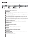
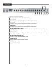
Rear Panel
23
28
29
24
25
26
27
30
23
25
24
26 27 28
29
30