


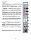
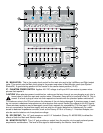

30. LEFT/MONO OUTPUT: This 1/4" jack provides an output from the Left Main mix to supply external
amp/speaker combinations. The level of this signal is determined by the Main Level control. When no plug is
connected to the Right Output (#31) then the right signal is mixed with the left, and both can be accessed at
the Left/Mono Output. This works well when you use the internal amps for monitor and external amps for
Main. Only one patch cord is required to get the Main out to the external amp.
31. RIGHT OUTPUT: This 1/4" jack provides an output from the Right Main mix to supply external
amp/speaker combinations. The level of this signal is determined by the Main Level control.
32. POWER AMP INPUTS: Plugging into these jacks allows the user to go directly into the Graphic
Equalizer, then into its respective power amplifier channel.
33. POWER LED: The power on LED indicator will light when the unit is powered.
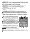
AC POWER AND POWER AMPLIFIER SECTION:
34. A/C POWER INLET: This is the receptacle for an IEC line cord, which provides AC power to the
mixer/amplifier. Connect the line cord to this connector to provide power to the unit. Damage to the
equipment may result if improper line voltage is used (see line voltage marking on unit).
35. POWER: The mixer’s main power switch. The power on LED indicator (#33) will light when the unit is
powered.
36. FUSE: This is the main safety fuse for the AC line voltage. Only
replace the fuse with one the exact same type and rating. IF THE
FUSE CONTINUES TO OPEN, DO NOT OVER FUSE. TAKE
THE UNIT TO AN AUTHORIZED PEAVEY SERVICE CENTER!
37. PARALLEL LEFT/RIGHT SPEAKER OUTPUTS: These 1/4" jacks
are the amplifier’s output. By connecting a speaker cable to this
jack and to a speaker cabinet, you complete the signal chain. You
will notice that there are two pairs of jacks with another jack in the
middle. The two pairs are your two (stereo) amp outputs. Two cabinets
can be connected to each channel, as long as the combined impedance
of the cabinets is not less than 4 ohms. (i.e., two 8 ohms cabinets in
parallel = 4 ohms, four 16 ohms speakers in parallel = 4 ohms, etc.).
38. BRIDGE OUTPUT (XR 684 only): The bridge output of the XR
684 allows the power of the left and right amplifiers to be combined into
one mono output in applications where only one speaker will be used.
To use the bridge output, the system mode switch must be in the
Left/Right position. Connect an 8 ohm minimum impedance speaker to
the center bridge output jack.
CAUTION: When using the bridge output no other speakers should be connected to the adjacent parallel
speaker outputs. In addition, the minimum load for the XR 684 in bridge mode is 8 ohms. Do not allow
the total impedance to drop below 8 ohms or serious damage to the amplifier may occur.
34
36
35
38
37
37
8