


4
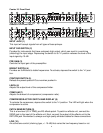
INPUT JACK (1)
This input will accept signals from all types of bass pickups.
INPUT PAD SWITCH (2)
Provided for instruments that have extremely high output, which can result in overdriving
(distorting) the input stage. Depressing the switch to its “in” position reduces the level of the
input signal by 10 dB.
PRE GAIN (3)
Controls the input gain of the preamplifier.
BRIGHT SWITCH (4)
Provides an 8 dB boost to treble frequencies. To activate, depress the switch to the “in” posi-
tion.
CONTOUR SWITCH (5)
Defeats the preset special EQ curve when pushed in.
LEVEL (6)
Adjusts the output level of the compressor/limiter.
COMP/LIM (7)
Adjusts the amount of compression (compression ratio).
COMPRESSOR ACTIVE SWITCH AND DISPLAY (8)
To activate the compressor, depress the switch to the “in” position. The LED will light when the
compressor is active.
PATCH SEND/RETURN (9)
This is a low-level (0.3 V RMS) pre-EQ effects patch. To patch an effects unit, connect the
SEND jack to the input of the effects unit. Next, connect the output of the effects unit to the
RETURN jack. Remember to always use high-quality shielded cables for these connections.
LOW (10)
An active tone control (shelving type, +/- 15 dB) that varies the low-frequency boost or cut.
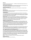
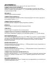
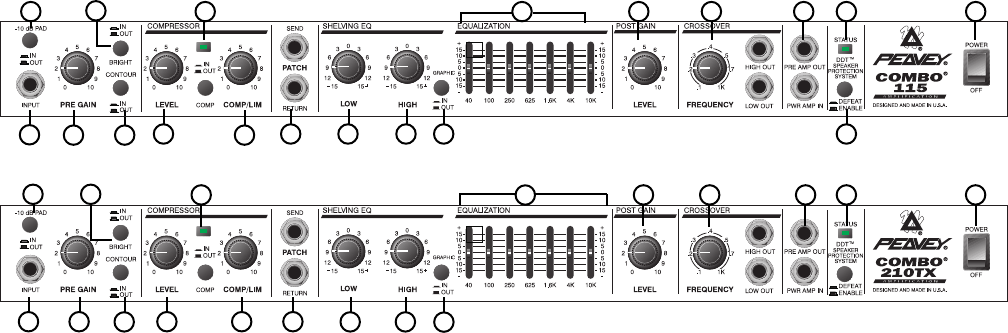
Combo 210TX Front Panel
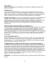
Combo 115 Front Panel
1 3 7
9
10 11 12
18
5
14 15 16 17 1913
12
1110
9763
82
4
1 5
2
4
8
13 14 15 16 17 19
6