


shall be available on all channels
and be switched on inputs 1 and
2. There shall be included a
security cover protecting the main
controls on the front panel with
marking zones for each input. The
master section shall be equipped
with gain management computer
logic for seamless operation.
There shall be a balanced mic or
line master output with switch. In
addition, there is a master,
unbalanced auxilliary output.
There is a master/slave
linking connection and switch on
the back panel for connection to
additional Automix 4 units, and
also the Automix 2, as well as the
SMR
™
821 mixer. All audio
connections shall be made with
removable “euro” type connectors.
The mixer shall have a
frequency response of 75 Hz to 20
kHz +/- 1 dB. It shall have an EIN
of -128 dBu and the total harmonic
distortion shall be less than 0.1%
at +4 dBu (22 Hz to 22 kHz BPF).
The maximum line output level
shall be +21 dBu (hi-Z load),
+18 dBu (600 load).
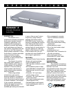
The unit shall be packaged in
a rugged metal chassis 19” wide
by 1.75” high by 9.38” deep. The
unit shall operate from 120 VAC,
60 Hx domestic and from 230
VAC, 50/60 Hz, export. The unit
shall be a Peavey Architectural
Acoustic Division model Automix 4.
THREE + TWO YEAR LIMITED
WARRANTY
NOTE: For details, refer to the
warranty statement. Copies of
this statement may be obtained by
contacting
Peavey Electronics Corporation,
P.O. Box 2898, Meridian,
Mississippi 39301-2898.
*US Patent no. 5,652,800
SPECIFICATIONS
Test Conditions:
120 Vrms, 60 Hz line voltage
maintained throughout testing.
Reference: 0 dBu = 0.775 Vrms.
INPUT SPECIFICATIONS
EIN:
-128 dBu (R
s
= 150 Ohms), typical
Preamp Gain Range:
10 dB - 65 dB (MIC inputs)
-13 dB - 44 dB (LINE inputs)
Input Impedance:
2K Ohms (MIC inputs)
>10K Ohms (LINE inputs)
>10K Ohms (INSERT inputs)
Priority (channels 1 and 2):
0 dB to 9 dB
Phantom Power:
+48 Volts
Input sensitivity:
MIC inputs -61 dBu
LINE inputs -40 dBu
INSERT inputs +4 dBu
Maximum Input Level:
MIC inputs +12 dBu
LINE inputs +30 dBu
INSERT inputs +21 dBu
Common Mode Rejection:
>70 dB 20 Hz – 20 kHz
OUTPUT SPECIFICATIONS
Frequency Response:
75 Hz (–3 dB) to 20 kHz (–1 dB)
(at +4 dBu; ref: 1 kHz; 75 Hz HPF)
THD:
<0.1% at +4 dBu
(22 Hz - 30 kHz BPF)
Signal/Noise:
(R
s
= 150 Ohms; 30 kHz LPF)
>85 dB (all controls fully CCW)
Output Impedance:
<200 Ohms
Nominal Output Level:
LINE level output +4 dBu
MIC level output –26 dBu
INSERT outputs +4 dBu
Maximum Output Level:
LINE level output +21 dBu (hi-Z load)
+18 dBu (600 load)
MIC level output –9 dBu (hi-Z load)
–12 dBu (600 load)
INSERT outputs +21 dBu (hi-Z load)
GENERAL SPECIFICATIONS
Channel Clip LED:
Red LED lights 2 dB before clipping
Also lights to indicate mute on
channel 1 and 2 inputs
Output Level Indicators:
Red LED lights 2 dB before clipping
Yellow LED lights at +4 dBu
Green LED lights at –16 dBu
Power Requirements:
120 Vrms, 60 Hz Domestic
230 Vrms, 50/60 Hz Export
15 Watts nominal
Dimensions:
1.75" x 19" x 9.38"
(45 mm x 483 mm x 238 mm)
Weight:
7.5 lbs
3.4 kg
Features and specifications subject to change without notice.
Peavey Electronics Corporation • 711 A Street • Meridian • MS • 39301
(601) 483-5376 • FAX (601) 486-1678 • http://aa.peavey.com
©2000 Printed in the U.S.A. 6/00
80304715