


Crest Audio CK Power Processing Amplifiers Page 7
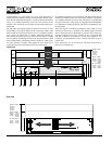
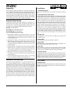
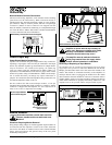
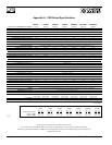
Network Bay.
Network Module Controls/Connections.
CK Power Processing amplifiers come standard with a blanking
panel fixed over the Network bay. When a Network module is
installed in this bay, network connection is made via a pair of three-
pin connectors. They are wired in parallel, and form a loop-through
connection. (Mates for these connectors are shipped with the
Network module.) Network bus addressing is accomplished through
use of the Hi and Lo Address dials. Refer to module documentation
for exact connection and control information.
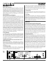
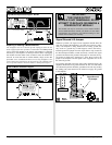
Power/Output Bay.
Power/Output Module Connections.
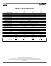
Speakers are connected using the Output Barrier Strip connectors.
Spade lugs, ring tongues or bare wire may be connected to the output
barrier strip elements. Spade Lug measurements for Output barrier
strip are as follows: .44" (11mm) screw spacing, .32" (8mm) lug
space. For output spade lugs, Panduit Part No. PNF 14-8LF-C (or
equivalent) is recommended. (Consult the wire gauge charts in theis
manual for speaker wiring recommendations.) Make sure the ampli-
fier is turned off before you change any output connections or
jumpers. Also ensure that the load impedance being connected is not
less than the amplifier's ability to drive it.
On the standard CC-STL Power/Output module, a four-pin
Sequential Turn-On/Turn-Off (STO) connector is suppled. A mating
connector is shipped with the amplifier. For more information on
STO, see the section on Sequential Turn-On/Off.
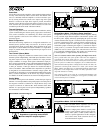
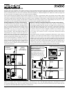
Module Removal.
Removable modules contain static-sensitive
devices; handle modules at static-safe work
stations!
Situations Requiring Module Removal
Only jumper setting changes or module upgrades require modules to
be removed from the amplifier. Contact Crest Audio Customer
Service for full details on module removal. The ‘General Module
Setup’ diagram indicates the general setup of the rear panel
module/bay configuration.
Amplifier is shown with the top cut away for
clarity only. Dangerous voltages exist inside,
and only a Crest Audio-certified service
technician should remove top cover !
The amplifier must be switched off and the
mains plug removed from the supply before
module removal operation is undertaken.
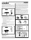
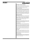
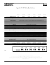
Removing or Replacing an Input Module.
The amplifier must be switched off and unplugged from the mains
supply before this operation is undertaken. Remove the four #8 3/8"
Phillips pan head sheet metal screws that secure the module to the
chassis. The module is connected electrically to the amplifier via
multi-pin ribbon cables. Unplugging the module from the ribbon
cable connectors frees the module for removal. To insert the same or
another module, simply reverse this procedure, making sure that any
ribbon cable connectors are properly and securely seated. Note: The
amplifier must not be operated without an Input module in place.
0
8
1
9
2
A
3
B
4
C
5
D
6
E
7
F
0
8
1
9
2
A
3
B
4
C
5
D
6
E
7
F
Model
Name
CKS 100
CKS 200
CKS 400
CKS 800
CKS 800-2
CKS 1200-2
CKS 1600-2
Output Power
@8Ω/Ch.
50W
100W
200W
400W
400W
600W
800W
Model
NC-NXS
Hi
Data
Lo
Crest Audio Inc.
100 Eisenhower Dr.
Paramus, New Jersey 07652 USA
Designed & manufactured in the USA by:
Network
+–
+–
Address
Model
Name
CKV 100
CKV 200
CKV 400
CKV 800
CKV 1600
CKV 2400
Output Power
@70.7V
50W
100W
200W
400W
800W
1200W
NexSys Network
Connectors
Network Bus
Address Selectors
Level
B
Level
A
Input A
Input B
+
+
–
–
7
8
9
5
2
0
1
3
4
6
10
7
8
9
5
2
0
1
3
4
6
10
Model
CC-IPB
SEE INSTRUCTION MANUAL
Model
CC-BLK
Designed & manufactured in the USA by:
Crest Audio Inc.
100 Eisenhower Dr.
Paramus, New Jersey 07652 USA
Model
Name
CKS 100
CKS 200
CKS 400
CKS 800
CKS 800-2
CKS 1200-2
CKS 1600-2
Output Power
@8Ω/Ch.
50W
100W
200W
400W
400W
600W
800W
Model
Name
CKV 100
CKV 200
CKV 400
CKV 800
CKV 1600
CKV 2400
Output Power
@70.7V
50W
100W
200W
400W
800W
1200W
S
2 WIRING
BE USED
p
ut
a
l
nd
p
er
Model
CC-STL
NEC
CLASS 2 ONLY
Com
Out
In
+8 to 18VDC
20 mA
CLASS 2 WIRING
MAY BE USED
Output
A
B
+
+
–
–
Signal
Ground
Lift
Jumper
Output Barrier Strip
Sequential Turn-On/Off
(STO) Connector
Network Module
If Load Monitoring is
employed, an additional ribbon
cable will be located here.
Input Module
Power/Output Module
Connections Diagram.
Input Module Removal Diagram - CC-IPB.
Network Bay Controls/Connections Diagram.
General Module Setup Diagram.