


6
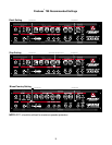
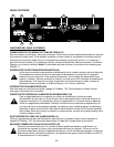
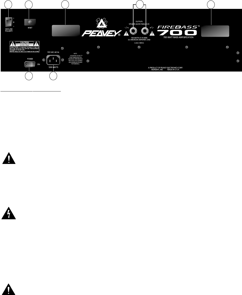
REAR PANEL FEATURES
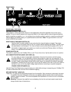
GROUND POLARITY SWITCH (27)
Three position, rocker-type switch, which for most applications should be operated in the center (zero)
position. If hum or noise is present with the ground switch in the center position, place the ground polarity
switch to positive or negative (+ or -) to minimize hum; should a problem continue, consult your authorized
Peavey dealer, the Peavey factory, or a qualified service technician. Note: The ground switch is not func-
tional on 220/240 volt models.
RESET/CIRCUIT BREAKER SWITCH (28)
Use this switch to restore power to your unit when the internal breaker is tripped. The proper
method is to turn the power switch to the “off” position before resetting the breaker. To reset, push
the reset button in and release it. Turn the unit back on and confirm that the power LED is on. If
the breaker is tripped again upon power-up, consult your authorized Peavey dealer, the Peavey
factory, or a qualified service technician.
POWER SWITCH (29)
This switch is used to turn the FireBass 700 on or off. To turn the unit on, flip the switch to the “on” position.
IEC CONNECTOR/DETACHABLE LINE CORD (30)
For your safety, we have incorporated a detachable, three-wire line (mains) cord with proper
grounding facilities. It is not advisable to remove the ground pin under any circumstances. If it is
necessary to use the amp without proper grounding facilities, suitable grounding adaptors should
be used. Greatly reduced shock hazard exists when the unit is operated with properly grounded
receptacles. Connect the IEC plug of your cord to the IEC socket on the rear of your unit. Refer to
the back of your unit for the proper voltage required before connecting to a power receptacle.
POWER CORD RETAINERS (31)
Use the Power Cord Retainers to wrap and store your cable while storing or transporting your FireBass 700.
It is best to disconnect the cord from the unit before wrapping.
SPEAKER OUTPUT JACKS (32)
These two 1/4" jacks provide the powered signal from the amplifier. Each connector is electrically the same
(in parallel). Use one of the jacks to connect your speaker cabinet and the other to add a second
speaker cabinet in parallel. The minimum speaker load impedance is 2 ohms (or two 4 ohm speak-
ers in parallel).
Warning: To prevent the amplifier from overheating, the front fan and rear-located vents should
always remain clear of obstructions.
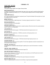
REAR PANEL
27
28
31
31
29
30
32