


Architectural and
Engineering Specifications
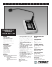
The Station Four shall have four momen-
tary non-programmable buttons.
Programming for these buttons shall occur
at the PageMatrix Controller and in the
MediaMatrix pasha.ini file and view file.
The buttons shall light up when pressed,
or have a multi function LED beside them
indicating ÒReadyÓ status. An indicator
shall also be present, indicating a ÒZone
BusyÓ status. The multi function LED can
also serve as the
Ò
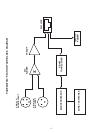
BusyÓ indicator. The
unit shall have a 3-pin XLR connector on
the front panel for audio. The unit shall
have a 5-pin XLR connector on the back
panel for a keyed microphone, three pins
for audio, and two pins for the Òkeyed micÓ
closure. The closure of the Òkeyed micÓ
shall be integral to the final paging
function and shall also act as a release
for the current zone requested. The unit
shall have a microphone preamplifier and
supply +48V phantom power to the mic.
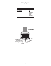
The unit shall communicate to the
PageMatrix Controller via RJ45 style
connector. The communications cable
CATEGORY 5 carries DC power, line
level audio, and the RS485 serial data.
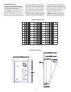
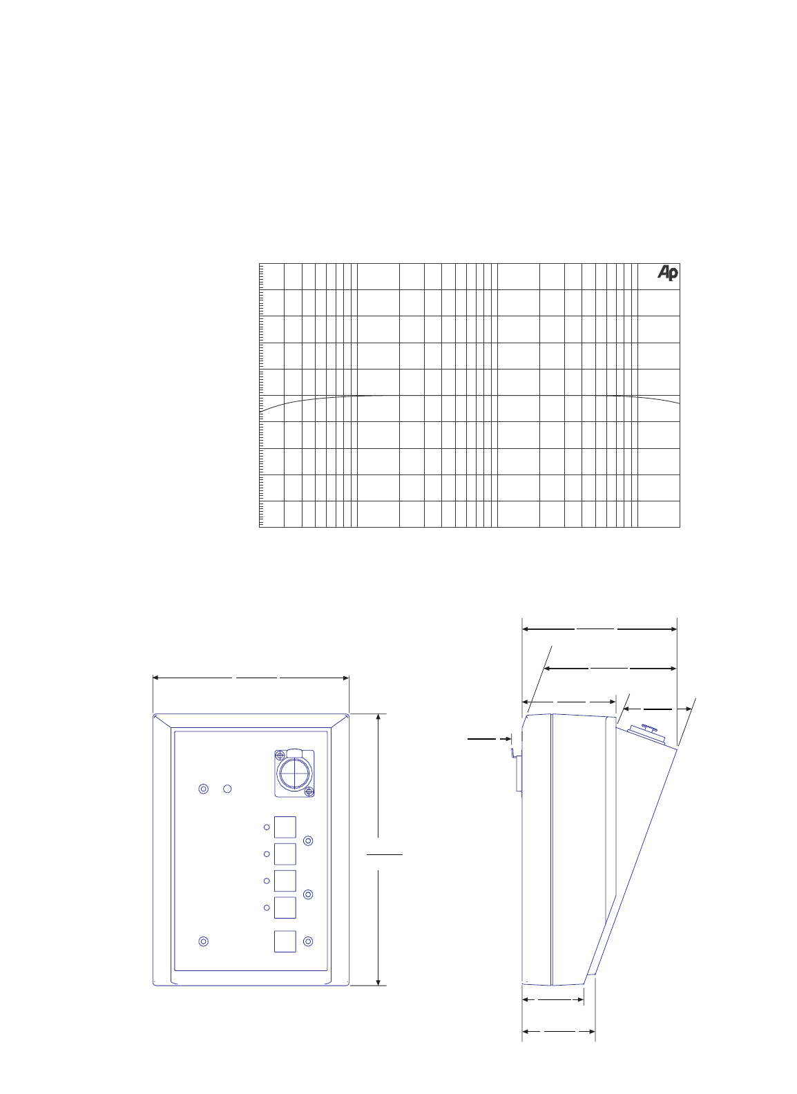
-10
+10
-8
-6
-4
-2
-0
+2
+4
+6
+8
d
B
20 20k50 100 200 500 1k 2k 5k 10k
Hz
Frequency Response
5.123"
13.01cm
7.086"
18.0cm
.274"
.70cm
2.449"
6.22cm
3.993"
10.14cm
4.040"
10.26cm
1.908"
4.85cm
1.607"
4.08cm
1.693"
4.30cm
Mechanical Diagram
2