


8. PHONO INPUT GROUND SCREW
Grounds from external turntable(s) should be connected at this point for a proper input connection.
9. MIC 1 INPUT
The Mic 1 Input is located on the top of your PM One. (See diagram on back.) The Mic 1 Input is a
balanced, low impedance controlled by the Microphone Fader (11). The Voice-over Switch (12) can
be placed in the TALK position while the Mic 1 Input is active to temporarily drop the music level by
12 dB.
10. MIC 2 INPUT
The Mic 2 Input is a balanced, low impedance TRS 1/4" input controlled by the Channel Fader (13)
of Channel 4. The Channel Input Select Switch for Channel 4 must be in the MIC 2 position for Mic
2 to be active. The Mic 2 input is located on the rear of the unit (see diagram on Page 4.)
6
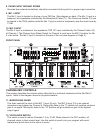
FRONT PANEL
19
21
19 22
15
16
24
26
2325
18
17
12
11
13
14
18
20
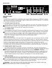
CHANNEL/MIC CONTROLS
This section describes the controls which affect the four individual channels and the Mic1/Mic 2
inputs. Refer to the diagram above for physical locations.
11. MICROPHONE FADER
This fader controls the level of the MIC 1 Input (9) only. The MIC 2 Input (10) is an optional
microphone input placed on Channel 4. Placing the fader in the Ò0Ó position will produce minimum
gain or no signal. Moving the fader to the Ò10Ó position will give maximum gain or the highest
output signal.
12. VOICE-OVER SWITCH
This switch is used to reduce Channels 1-4 by 12 dB. When placed in the OFF position, all
channels return to their normal level. Use this switch to punch into your program with vocal
material and punch back out to return to music.