


6
7
See Neumann bulletin No. 68832... “Phantom 48 Vdc
Power Supplies”.
NN
NN
N
4848
4848
48
i-2 (230i-2 (230
i-2 (230i-2 (230
i-2 (230
V)V)
V)V)
V) ............ blk.............................. Cat. No. 06500
NN
NN
N
4848
4848
48
i-2 (117i-2 (117
i-2 (117i-2 (117
i-2 (117
V)V)
V)V)
V) ............ blk.............................. Cat. No. 06502
4.3 Battery Operation
In contrast to its predecessor U 87 i, the U 87 Ai mi-
crophone has no built-in battery current supply. If a
mains power source is not available, power can be sup-
plied by one of the units BS 48 i (for one microphone)
or BS 48 i-2 (for two microphones).
Both units deliver 48 V ± 1 V, at 5 mA maximum,
and are powered by a 9-volt monobloc battery type
IEC 6 F 22. See Neumann bulletin No. 68832... “Phan-
tom 48 Vdc Power Supplies”.
Modulation polarity at the power supply output is iden-
tical with that at the microphone.
BSBS
BSBS
BS
4848
4848
48
ii
ii
i (for one microphone) ........................Cat. No. 06494
BSBS
BSBS
BS
4848
4848
48
ii
ii
i
-2-2
-2-2
-2 (for two microphones) .................Cat. No. 06496
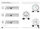
5. Operation with Unbalanced or
Center Tap Grounded Inputs
The 48 V phantom powering units BS 48 i, BS 48 i-2
and N 48 i-2 have dc-free outputs, so that no trans-
former is required for connecting to an unbalanced
input.
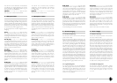
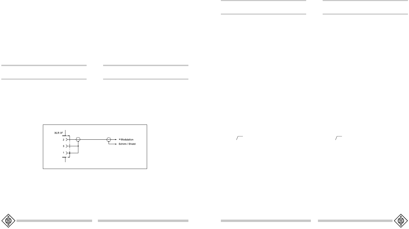
In the case of the U 87 Ai condenser microphone
pin 2 is the hot phase, and pin 3 must be connected
to earth (see Fig. 1).
In the case of many oth-
er phantom powering
units (except those men-
tioned above), not only
the modulation leads to
the microphone, but also
the outgoing modulation
leads from the powering
unit, are at the potential
of the feed voltage
(+48 V). This is of no significance for the balanced,
floating amplifier and mixing console inputs in general
studio use.
On the other hand, the feed voltage will be short-
circuited when connected to unbalanced or center tap
grounded amplifier inputs, and no operation will be
possible.
Siehe Neumann-Druckschrift 68832... „48 V-Phantom-
speisegeräte“.
NN
NN
N
4848
4848
48
i-2 (230i-2 (230
i-2 (230i-2 (230
i-2 (230
V)V)
V)V)
V) ............ sw .............................Best.-Nr. 06500
NN
NN
N
4848
4848
48
i-2 (117i-2 (117
i-2 (117i-2 (117
i-2 (117
V)V)
V)V)
V) ............ sw .............................Best.-Nr. 06502
4.3 Batteriespeisung
Das Mikrophon U 87 Ai besitzt im Gegensatz zum
Vorgängermodell U 87 i keine eingebaute Batteriespei-
sung mehr. Für die netzunabhängige Stromversorgung
von Neumann-Kondensatormikrophonen steht das Bat-
teriegerät BS 48 i (für ein Mikrophon) oder BS 48 i-2
(für zwei Mikrophone ) zur Verfügung.
Beide Geräte liefern 48 V ± 1 V, maximal je 5 mA
und werden jeweils von einer 9-Volt-Blockbatterie
Typ IEC 6 F 22 gespeist. Siehe Neumann-Druckschrift
88832... „48 V-Phantomspeisegeräte“.
Die Zuordnung der Mikrophonanschlüsse und die Po-
larität der Modulationsadern ist am Ausgang der Spei-
segeräte die gleiche wie am Mikrophon.
BSBS
BSBS
BS
4848
4848
48
ii
ii
i (für ein Mikrophon) .........................Best.-Nr. 06494
BSBS
BSBS
BS
4848
4848
48
i-2i-2
i-2i-2
i-2
(für zwei Mikrophone) ...............Best.-Nr. 06496
5. Betrieb an unsymmetrischen oder
mittengeerdeten Eingängen
Die 48 V-Phantomspeisegeräte BS 48 i, BS 48 i-2 und
N 48 i-2 haben gleichspannungsfreie Ausgänge, so daß
für den Anschluß an einen unsymmetrischen Eingang
kein Übertrager erforderlich ist.
Beim U 87 Ai ist Pin 2 die heiße Phase, und Pin 3
muß für unsymmetrische Eingänge an Masse gelegt
werden (siehe Abbildung 1).
Bei vielen anderen als
den o.g. Phantomspeise-
geräten liegen nicht nur
die Modulationsleitungen
zum Mikrophon auf dem
Potential der Speisespan-
nung von +48 V, sondern
auch die vom Speisege-
rät abgehenden Modula-
tionsleitungen. Für die in
der Studiotechnik allgemein üblichen symmetrischen
und erdfreien Verstärker- und Mischpulteingänge ist
dies ohne Bedeutung.
Dagegen wird die Speisespannung beim Anschluß an
unsymmetrische oder mittengeerdete Verstärkerein-
gänge kurzgeschlossen, und es ist kein Betrieb mög-
lich.
Dann bestehen folgende Lösungsmöglichkeiten:
a) In mittengeerdeten Geräten mit Eingangsübertra-
ger (z.B. einige NAGRA-Geräte) kann die betreffen-
de Erdverbindung fast immer ohne Nachteile für die
Funktion des Gerätes aufgetrennt werden.
b) In jede abgehende Modulationsleitung kann zur
Abblockung der 48 V-Gleichspannung eine RC-Kom-
bination eingefügt werden (siehe Neumann-Informa-
tion Nr. 84 221).
6. Zerlegen des Mikrophons und
Meßeingang
Nach Linksdrehen der Überwurfmutter am unteren Teil
des Mikrophons läßt sich das Gehäuserohr abziehen,
und es wird eine rote Buchse sichtbar. Über diese kann
in die zum Kapselfußpunkt führende Leitung eine Ton-
frequenzspannung eingeschleift werden, die den Ver-
stärkereingang über die Kapselkapazität in gleicher
Weise beaufschlagt, wie dies beim Auftreffen eines ent-
sprechenden Schallwechseldruckes der Fall wäre.
Die meisten elektrischen Daten des Mikrophonverstär-
kers wie Verstärkung, Frequenzgang und Aussteuerbar-
keit können so direkt überprüft werden. Der Eingangs-
widerstand des Meßeinganges ist ca. 600 Ohm.
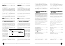
Rot: zum Kapselfußpunkt.
Sollwerte für das U 87 Ai sind (Toleranz ± 1 dB):
Spannungsverstärkung
(1 kHz, Abschluß 1 kOhm ) ............................................ 0 dB
Rel. Verstärkung bei 40 Hz
(bezogen auf den Wert bei 1 kHz)........................... –3 dB
Rel. Verstärkung bei 40 Hz
(Schalter ).................................................................. –18 dB
Rel. Verstärkung bei 16 kHz ......................................... –4 dB
Maximale Eingangswechselspannung
(1 kHz), bei der der Klirrfaktor
unter 0,5 % sein soll.................................................390 mV
eff
Stromaufnahme bei 48 V............................0,8 ± 0,05 mA
Störspannungen (DIN 45 405, CCIR 468-3;
0 dB : 0,775 V; Toleranz +1 dB):
Unbewerteter Störspannungspegel ................ –103 dB
qs
Bewerteter Störspannungspegel.....................–101 dB
qps
This can be circumvented as follows:
a) In center tap grounded equipment with input
transformer (e.g. some NAGRA units), the earth lead
can almost always be disconnected without affecting
the function of the equipment.
b) In every outgoing modulation lead, an RC net-
work can be incorporated to block the 48 Vdc voltage
(See Neumann-Information no. 84 222).
6. Disassembling of the Microphone
and Test Input
Unscrew the large lower ring of the microphone; the
conical housing tube can then be withdrawn downwards
and a red socket can be seen. This socket enable an
audio frequency test signal to be applied to the ampli-
fier input via the capsule capacitance in the same way
as a corresponding change in sound pressure.
Most of the electrical data of the microphone amplifi-
er, such as gain, frequency response, self noise, and
modulability can thus be directly tested. Input imped-
ance of the measuring input: 600 ohms approx.
Red: to capsule base-point.
The nominal values for the U 87 Ai are as follows
(tolerance: ± 1 dB):
Voltage gain
(1 kHz, 1 kOhm termination) ......................................... 0 dB
Rel. gain at 40 Hz,
(ref. 1 kHz)............................................................................... –3 dB
Rel. gain at 40 Hz,
(switch ) ..................................................................... –18 dB
Rel. gain at 16 kHz.............................................................. –4 dB
Maximum input ac voltage (1 kHz)
at which the THD should be less
than 0,5 % .................................................................... 390 mV
rms
Current consumption at 48 V .................0.8 ± 0.05 mA
Nominal self-noise level (CCIR 468-3,
Reference: 0.775 V, peak to peak, tolerance: +1 dB):
Unweighted self-noise level................................ –103 dB
qs
Weighted self-noise level................................... –101 dB
qps
Abbildung / Figure 1