LOGIC INPUT
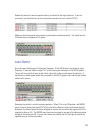
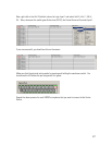
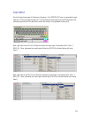
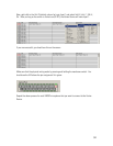
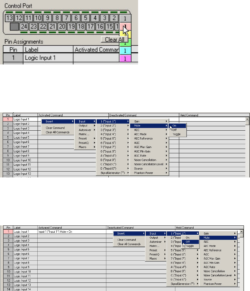
Go to the Logic Input page of Conference Composer. If the SWITCH OUT wire is connected to Logic
Input pin 1, then you need to assign Pin 1 by left-clicking the desired pin in the DB-25 graphic and
selecting the pink color (The pink color means that the pin is not grouped to other pins).
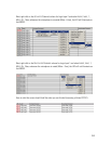
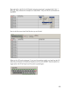
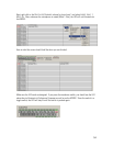
Now, right click in the A
CTIVATED COMMAND column for Logic Input 1 and select INSERT, INPUT, 1,
M
UTE, ON. Now, whenever the switch goes Active Low (0V DC), the Vortex Device will mute
Input 1.
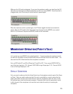
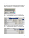
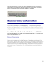
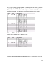
Now, right click in the D
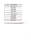
EACTIVATED COMMAND column for Logic Input 1 and select INSERT, INPUT, 1,
M
UTE, OFF. Now, whenever the switch goes Active High (+ 5V DC), the Vortex Device will unmute
Input 1.
31


