


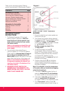
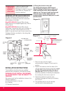

6. The shower is designed to have an open
outlet and should only be used with Redring
recommended fittings.
WARNING: DO NOT FIT A TAP ON THE
SHOWER OUTLET. TAKE CARE TO AVOID
RESTRICTING THE OUTLET OF THE
PRESSURE RELIEF DEVICE. (SHOWN IN
DIAGRAM 2).
8
C) Electrical
The electrical installation must be in accordance
with current BS. 7671 (I.E.E. regulations) and/or
local regulations.
1. The shower is designed for a single phase
A.C. electrical supply of:
Please check the rating plate on the unit to see
what details apply to your unit.
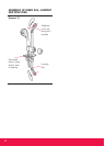
Model Variant Rated Voltage
Expressions 570 8.5 /7.8 kW 240 / 230 V
(8.5 kW) 8.5 kW 230 V
Expressions 570 9.5 /8.7 kW 240 / 230 V
(9.5 kW) 9.5 kW 230 V
2. Cable Sizes
Expressions 570 9.5/8.7kW, 240/230V, version
may be able to use 6mm
2
cable if BS 7671:
Method 1 (clipped direct) is used. The maximum
cable run for all models above will depend upon
site conditions.
REMEMBER TO UPRATE THE CABLE IF IT RUNS
IN THERMAL INSULATION IN A LOFT.
3. In order to provide a means of isolation, the
heater MUST BE permanently connected to
the electricity supply through a double pole
linked switch with a contact gap of 3mm
mounted in a convenient position. We
recommend ceiling switches.
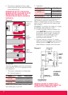
4. Cut back cable as in diagram 10, connect
cable to terminal block making sure that all the
retaining screws are VERY tight and that no
cable insulation is trapped under the screws.
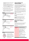
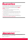
Diagram 8
A
B
C
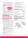
Simply push
in tube to
attach
Tube is
secured in
position
Push in
collet to
release tube
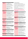
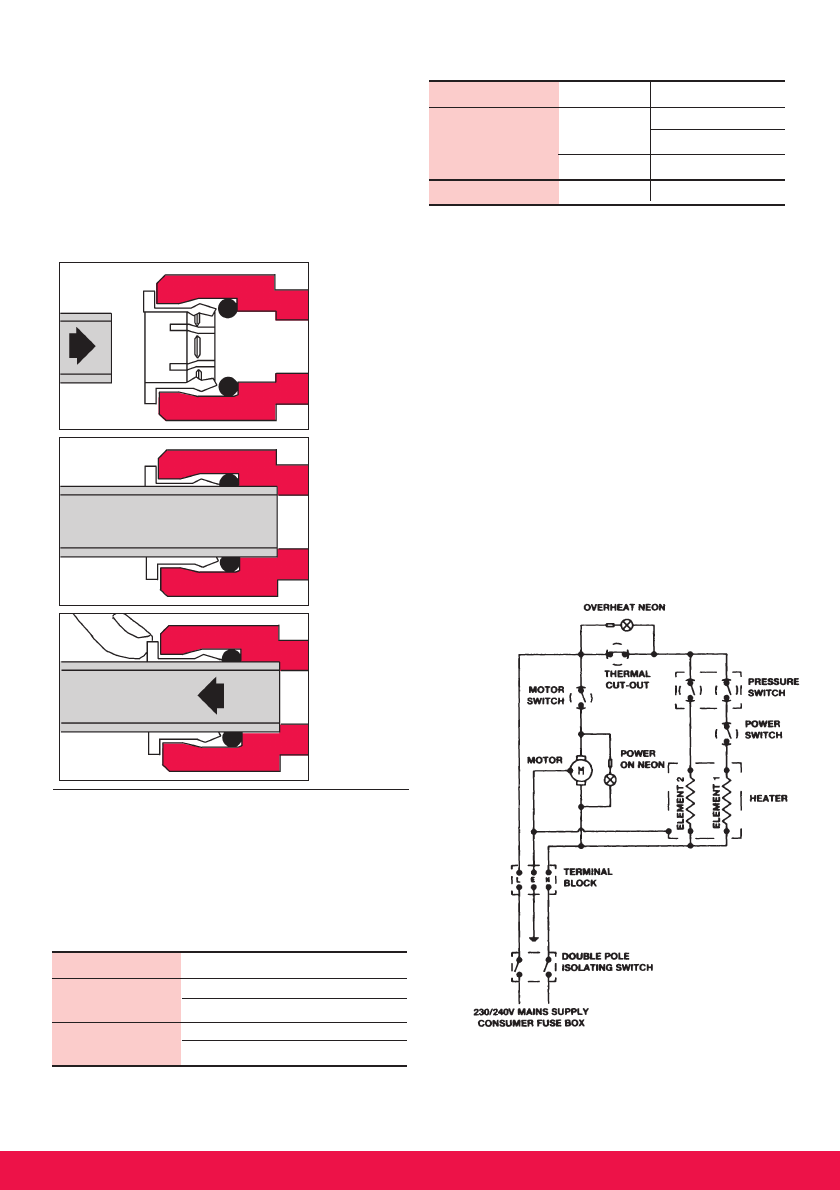
Diagram 9
SCHEMATIC
WIRING
DIAGRAM
WARNING: FAILURE TO COMPLY WITH
THESE INSTRUCTIONS COULD RESULT IN A
FAILURE OF THE TERMINAL BLOCK.
Model Cable Sizes Fuse Type
Exp. 570 6mm
2
40 A Cartridge Fuse
(8.5 kW) Type 'A' MCB
10mm
2
45 A Cartridge Fuse
Exp. 570 (9.5 kW) 10mm
2
45 A Cartridge Fuse