


15
Panel Descriptions
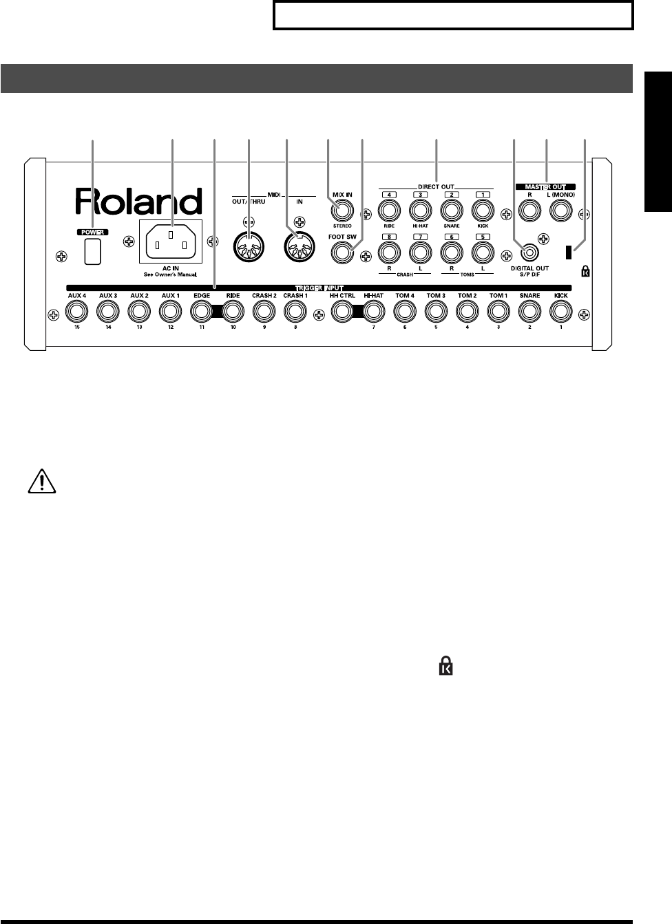
An Overview of the TD-20
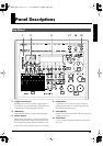
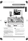
fig.rear_50
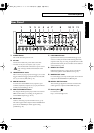
1.
POWER Switch
This switch turns the power on/off.
2.
AC Inlet
Connect the included AC power cable to this inlet.
* For details on the power consumption, refer to p. 103.
The unit should be connected to a power source
only of the type marked on the bottom of the
unit.
3.
TRIGGER INPUT Jacks
Here is where you plug in pads, kick triggers, or acoustic
triggers. With dual trigger pads (PD-125/120/105/80R/
9/8/7), use a stereo (TRS) cable (p. 18).
4.
MIDI IN Connector
To connect an external MIDI source (sequencer, pad
controller, keyboard, computer, etc.) to play the TD-20’s
sounds, or to load data (pp. 74–77).
5.
MIDI OUT/THRU Connector
For using the TD-20/pads to play sounds in an external
MIDI sound module, or recording/saving data to an
external MIDI sequencer (pp. 74–77).
6.
MIX IN Jack
Used for connecting any external audio source (p. 19).
This audio signal will be output from the MASTER OUT
jacks and/or PHONES jack. Other signal routing
possibilities (p. 78).
7.
FOOT SWITCH Jack
Optional foot switches (such as BOSS FS-5U) give you
access to a variety of functions like selecting drum kits,
sequencer start/stop, etc. Using an optional PCS-31 cable
(standard insert cable), two foot switches can be utilized
at the same time (p. 79).
8.
DIRECT OUT Jacks
Individual outputs have a variety of uses. The TD-20
offers many options. See the SETUP screen (p. 78).
9.
MASTER OUT Jacks
For connecting to your amp/audio system. For monaural
output, use the MASTER OUT L (MONO) jack.
10.
DIGITAL OUT Connector
This coaxial-type digital out connector sends the same
audio signal as is output from MASTER OUT jacks.
11.
Security Slot ( )
For retail store use.
http://www.kensington.com/
Rear Panel
12
8 93 4 5 7 11106
TD-20_Ref_e.book 15 ページ 2004年3月5日 金曜日 午後7時3分