


INTRODUCTION
Thank you for your purchase of the MX310. This unit is designed and
manufactured to mix three microphones together and send their com-
bined signals out to a single transformer-balanced XLR output. The indi-
vidually switchable phantom power and low-cut switches provide the fi nal
touches which make the MX310 a valuable tool for any sound reinforce-
ment, musical, recording, or install application.
INSPECTION
1. Unpack and Inspect the MX310 package.
Your MX310 was carefully packed at the factory in a protective carton.
Nonetheless, be sure to examine the unit and the carton for any signs
of damage that may have occurred during shipping. If obvious physical
damage is noticed, contact the carrier immediately to make a damage
claim. We suggest saving the shipping carton and packing materials for
safely transporting the unit in the future.
2. For warranty registration go to our website: WWW.ROLLS.COM
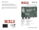
DESCRIPTION
REAR PANEL
Mic Input: 1 - 3: XLR balanced inputs for connection to any standard
dynamic or condenser microphone.
Output: Transformer balanced XLR output jack for connection to the next
device in the signal chain such as a mixer, signal processor or amplifi er.
MIC/LINE Switch: This switch adjusts the output XLR level from Mic or
Line level. This switch does not effect the Aux/Headphone Output.
FRONT PANEL
Mic Level 1 - 3: These controls adjust the level of the corresponding Mic
channel. The level varies from -infi nity (off) to +60 dB of gain (typical).
Phone/Aux: 1/8" TRS jack which may be connected to a pair of head-
phones for personal monitoring, or to an unbalanced input of a signal
processor or amplifi er.
Power LED: Indicates the MX310 is on.
Clip LED: Indicates that clipping is about to occur or occurring in the
MX310 circuitry. This LED begins to light 3dB below actual circuit clip-
ping.
Located on the right side of the unit is the +12 VDC power jack for
connection to the Rolls PS27 +12 VDC (outside of the ring is positive)
external power supply.
On the left side are the Phantom Power and Low-
Cut switches.
As shown here, under each number is a P indi-
cating Phantom Power, and an L which indicates
Low-Cut.
When the P switch is DOWN, the phantom power is ON, when it is UP,
the phantom power is OFF.When the L switch is UP, the low-cut is ON,
when it is DOWN, the low-cut is OFF.
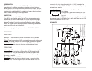
SCHEMATIC
PHNT PWR ON=DOWN
LOW CUT ON=UP
1 2 3
P L P L P L
1
Rolls Corporation
5968 S 350 W
Murray, Utah 84107
1
MX310.SCH 41310
22 April 2010
Title
Size: Document Number:
Date:
Rev:
Sheet of
MX310 MORMICS 3 CH MIC MIXER
FXa
LINE/HDPHONE
IN 9-15 VDC
HI
+VB
+VB
+VB
+V
+V
+V
+V
+V
+VB
+VB
+VB
CLIP
2
3
1
J4
JAPDC
C20
47U
R23
10K
C16
27PF
R3 332 1%
2 11
SW1B
SW DIP-6
P1
P100K
C5
503
R4 332 1%
R5
20K 1%
C3
470PF
R6
20K 1%
C4
470PF
R10 332 1%
4 9
SW1D
SW DIP-6
P2
P100K
C10
503
R11 332 1%
R12
20K 1%
C8
470PF
R13
20K 1%
C9
470PF
R17 332 1%
6 7
SW1F
SW DIP-6
P3
P100K
C15
503
R18 332 1%
R30
20K 1%
C13
470PF
R20
20K 1%
C14
470PF
R28
22K
D1
1N4001
Q1
2N3904
D3
LDRG
CR1
1N4148
CR2
1N4148
CR3
1N4148
D2
LDRG
R27
3.3K
R25
33K
R26
10K
R29
18K
R24
2K
5
6
7
8
U1B
4560
3
2
1
4
U2A
4560
5
6
7
8
U2B
4560
2
3
1
4
U3A
4556
C17
1K UF
Output Level
OUT
+VB
+V
1 2
3
J6
XLR M PC
C19
47U
R40
100K
R41
1K
CR4
1N4148
6
5
7
8
U3B
4556
LOW
C21
27PF
+VB
+VB
+VB
R21
10K
R14
10K
R31
4.7K
R33
4.7K
R35
10K
R7
10K
2
3
1
4
U1A
4560
CH 1
CH 2
CH3
VPHAN
VPHAN
R2
4.99K 1%
1 12
U1A
SW DIP-6
R1
4.99K 1%
1 2
3
J1
XLR F PC
R9
4.99K 1%
3 10
U1C
SW DIP-6
R8
4.99K 1%
1 2
3
J2
XLR F PC
R16
4.99K 1%
5 8
U1E
SW DIP-6
R15
4.99K 1%
1 2
3
J3
XLR F PC
C26
10U
C25
10U
C6
10U
C7
10U
C11
10U
C30
10U
C12
10U
C28
10U
C27
10U
C29
10U
C2
10U
C1
10U
R42
47K
C22
47U
Q2
2N3904
VPHAN
VPHAN
R32
330
R19
330
1
2
3
SW2A
DPDT
4
5
6
SW2B
DPDT
R34
100
R22
100
C18
47U
R36 10K
R37 10K
C24
1U
AUX IN
J7
JK3.5ST
J5
JK3.5ST
C23
503
801-263-9053