


+6
+50
MIC 1
MIC 2
MIC 3
LINE 1
-6 dB
LINE 2
-6 dB
LINE 3
-6 dB
5/RIGHT
7/RIGHT 9/RIGHT
4/LEFT/MONO 6/LEFT/MONO 8/LEFT/MONO
AUX 1
SEND
AUX 2
SEND LEFT OUT
RIGHT OUT
AUX 1
RET LEFT/MONO
AUX 1
RET RIGHT
PHANTOM
PWR
dB
+6
+50
dB
+6
+50
dB
VOLUME 1
VOLUME 2
P
OWER
A
MPLIFIER RA2100B
MAINS AMPLIFIER
MONITOR AMPLIFIER
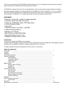
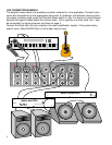
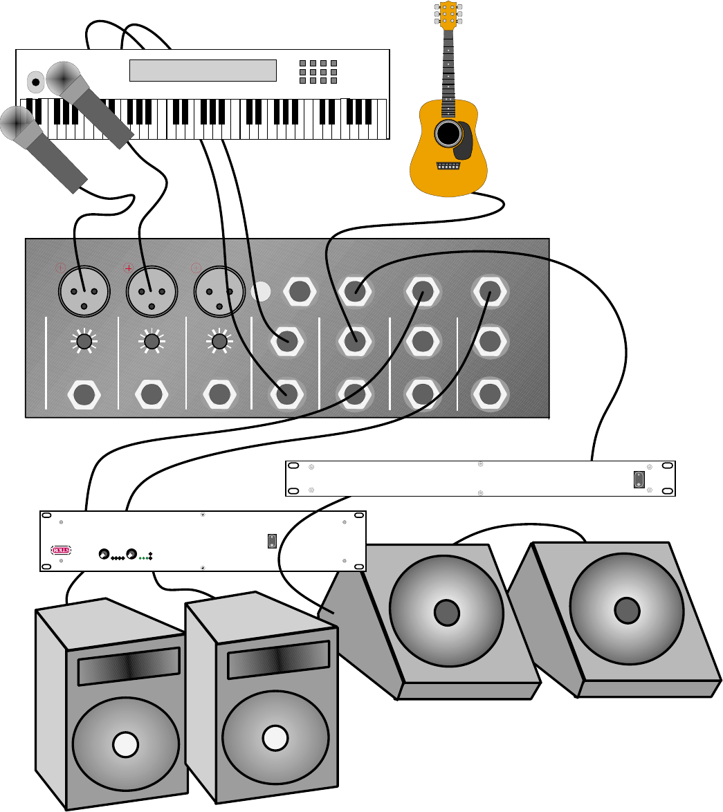
LIVE CONNECTION EXAMPLE
The diagram shown below is a possible connection scheme for a live application. Connect instru-
ments and microphones to the appropriate input jacks. If condenser microphones requiring phan-
tom power are being used, press the Phantom Power switch in. Aux 2 is used as a monitor output
because the signal is taken before the channel fader - this is typically a monitor send. Aux 1 may
be connected to a signal processor as shown on page 4.
Connect the Right and Left main outputs to the main amplification system. If the system being
used is mono, either MX902 Right or Left output may be used.
5