


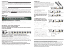

4. CHANNEL INSERT
For each channel you wish to have
the ability to insert into, you must fi rst
confi gure that channel’s 1/4” Input as
an INSERT. Follow the instructions
shown on the back page. Connect a
1/4” Tip-Ring-Sleeve INSERT cable
into the channel’s 1/4” jack, and to the
processor or other device you want the signal connected to.
2. CONNECTING TWO RM82
UNITS TOGETHER
Using a single RCA cable, connect from
the Pre-Fader Output of the “Slave” unit
to the Aux Bus input of the “Master” unit.
This “Master” unit’s Master Level control
will now adjust the overall level of both
units.
INTRODUCTION
Thank your for your purchase of the Rolls RM82 Mic Line eight channel audio mixer. It is
intended for sound reinforcement or studio applications where several microphones or
line sources need to be combined to a single output. Please review this manual for proper
operation.
INSPECTION
1. Unpack and inspect the RM82 box and package.
If obvious physical damage is noticed, contact the carrier immediately to make a damage
claim. We suggest saving the shipping carton and packing materials for safely transport-
ing the unit in the future.
2. Please visit our website at www.rolls.com and register your warranty at the “Register
Your Warranty Here” text, or complete the Warranty Registration Card and return it to the
factory.
DESCRIPTION
FRONT PANEL
NOTE: Descriptions for Channels 1 - 8 are identical.
TRIM: Adjusts the sensitivity of the XLR Microphone Inputs.
LEVEL: Adjusts the level of signal in the channel from off to +20 dB of gain.
TONE:Cuts the signal up to 12 dB, below 200 Hz when turned clockwise, or above 6 kHz
when turned counter-clockwise.
MASTER LEVEL: Adjusts the Main Output signal level.
pwr: LED indicating power is applied to the RM82.
Power Switch: Applies power to the unit. Please ensure the power cable is connected to a
properly grounded AC outlet.
REAR PANEL
MAIN OUTPUT: XLR balanced jack containing the RM82 main output signal.
PRE-FADE OUTPUT: RCA jack for connection to another RM81 Aux/Bus Input or to
another device such as a recorder.
AUX INPUT: RCA jack which connects directly to the RM81 mix bus. The jack may be
connected to another RM81 Pre-Fade Output - making this unit the “Master”.
PHANTOM POWER SWITCHES: 8 individual DIP switches for applying 48 Volts of
phantom power to the indicated channel’s XLR Input. The phantom power is for powering
condenser microphones. The Phantom Power switches are in the OFF position when the
RM82 is shipped from the factory.
CHANNEL INPUTS 1 - 8: 1/4” TS unbalanced, and XLR balanced input jacks.
The eight 1/4” jacks come from the factory confi gured as line inputs and are electrically
mixed with the XLR jacks. They may be used together if desired. These inputs may be
reconfi gured as either Direct Outputs, or Inserts. See page 4 for details.
CONNECTION
1.
MICROPHONE AND MAIN OUTPUT CONNECTION
Connect microphones to the XLR Inputs as shown here. If the
microphones are condenser type, and require phantom power
- remember to switch on (down) the corresponding Phantom
Power switch.
Connect the Output to the next device in your
signal chain.
3. CHANNEL DIRECT OUTPUT
For each channel you wish to have
Direct Output access, you must fi rst
confi gure that channel’s 1/4” Input as
a Direct Output. Follow the instruc-
tions shown on the back page.
Connect a 1/4” unbalanced Tip-Sleeve
cable to the channel’s 1/4” jack and to the next device you want the signal sent
to. Note, the channel’s signal will still be present at the RM82 Main Output.
A NOTE ABOUT ROLLS MICROPHONE PREAMPLIFIER CIRCUITS
The Rolls servo-balanced Microphone Preamps feature many advantages over other mic
preamps. Among these are simplicity of design, 40db or higher CMRR (common mode
rejection ratio) than transistor input mic preamps. This means much lower noise on long
input lines, and very low distortion at high gain. Discrete transistor preamps are non-linear
at high gains, but not our design. We feature a higher signal swing, which means our
preamps have more headroom before clipping.