


4
DUAL 15 BAND
EQUALIZER
0
6
6
12
12
0
6
6
12
12
0
6
6
12
12
0
6
6
12
12
0
6
3
-20
OFF
BYPASS
POWER
25 40 63 100 160 250 400 630 1K 1.6K 2.5K 4K 6.3K 10K 16K
25 40 63 100 160 250 400 630 1K 1.6K 2.5K 4K 6.3K 10K 16K
25 40 63 100 160 250 400 630 1K 1.6K 2.5K 4K 6.3K 10K 16K
25 40 63 100 160 250 400 630 1K 1.6K 2.5K 4K 6.3K 10K 16K
CH 2
LOW CUT
CH 2
0
6
3
-20
OFF
BYPASS
CH 1
LOW CUT
CH 1
-30-18 -6 0 +18+6-30-18 -6 0 +18+6
6
1
2
3
4
5
1
2
3
4
5
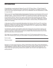
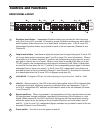
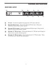
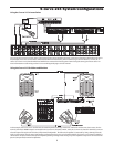
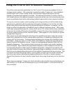
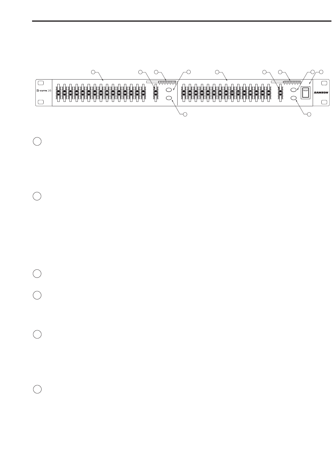
1 Equalizer level sliders - Independent Equalizer sliders are provided for each frequency
area (The S curve 215 provides 15 frequency areas).Calibration markings on either side of
each Equalizer slider allow you to cut or boost each frequency area. In the S curve 215,
independent Equalizer sliders are provided for each of the two channels (Channel A and
Channel B).
2 Output level sliders - Use these to adjust the output level of signal leaving the S curve 215
via its rear-panel output connectors (see C and E on page 5 for more information). When a
Level slider is at its center detented “0” position, the corresponding output signal is at unity
gain (that is, there is no cut or boost). When a Level slider is moved all the way up (to the
“+6 dB”) position, the corresponding output signal is boosted by 6 dB. When a Level slider
is moved all the way down (to the “∞” position), the corresponding output signal is infinitely
attenuated (that is, there is no signal). In the S curve 215, independent Level sliders are
provided for each of the two channels (Channel 1 and Channel 2). Note that the Level slid-
er is deactivated when the S curve 215 is in Bypass mode (see #5).
3 LEVEL METER - Six segment LED bar VU meter displaying the Input Level from –30dB to +18dB.
4 LOW CUT -
When pressed in, the LED in the switch lights yellow and an 80 Hz highpass filter
is applied to the signal, effectively removing rumble and other low frequencies. In the S
curve 215, independent HPF switches are provided for each of the two channels (Channel
1 and Channel 2).
5 Bypass switches - When not pressed in, the equalization circuitry is made inactive so that
the signal passes through unaffected, regardless of the settings of the Equalizer or Level
sliders. When pressed in, the LED in the switch lights green and the equalization circuitry
affects the signal as per the setting of the front panel Equalizer and Level sliders (see #1
and #2). In the S curve 215, independent Bypass switches are provided for each of the two
channels (Channel 1 and Channel 2).
6 Power switch - Use this to turn the power on and off.
Controls and Functions
FRONT PANEL LAYOUT