


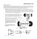
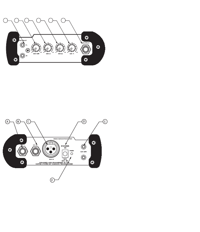
S mix Front and Rear Panel Layout
1
2
3
45
6
A CHANNEL 1 INPUT- 1/4-inch input for con-
necting Line/Instrument level signals.
B CHANNEL 2 INPUT- 1/4-inch input for con-
necting Line/Instrument level signals.
1L & R RCA OUTPUT - Left and Right
main mix OUTPUT on RCA con-
nectors.
2 CHANNEL 4/5 VOLUME - Control
knob used to adjust the level of
inputs 4 and 5.
4
3 CHANNEL 3 VOLUME - Control
knob used to adjust the level of
input 3.
4 CHANNEL 2 VOLUME - Control
knob used to adjust the level of
input 2.
5 CHANNEL 1 VOLUME - Control
knob used to adjust the level of
input 1.
6 TRS OUTPUT - Left and Right
main mix OUTPUT on TRS
(TIP/RING/SLEEVE) connectors.
C CHANNEL 3 INPUT- XLR mic-level
input for connecting standard
microphones.
DDCPOWER INPUT- Connect the
supplied power adapter here.
E CHANNEL 4/5 INPUTS- RCA inputs
for stereo line level signals.
FPOWER LED - Red LED will illumi-
nate when power is on indicating
the S mix is ready for operation.
Front Panel Layout
Rear Panel Layout