


12
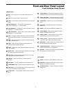
Operating the MDR624
BASIC OPERATION
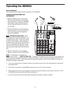
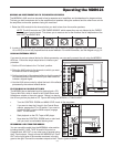
The following section explains the basic operation of the MDR624.
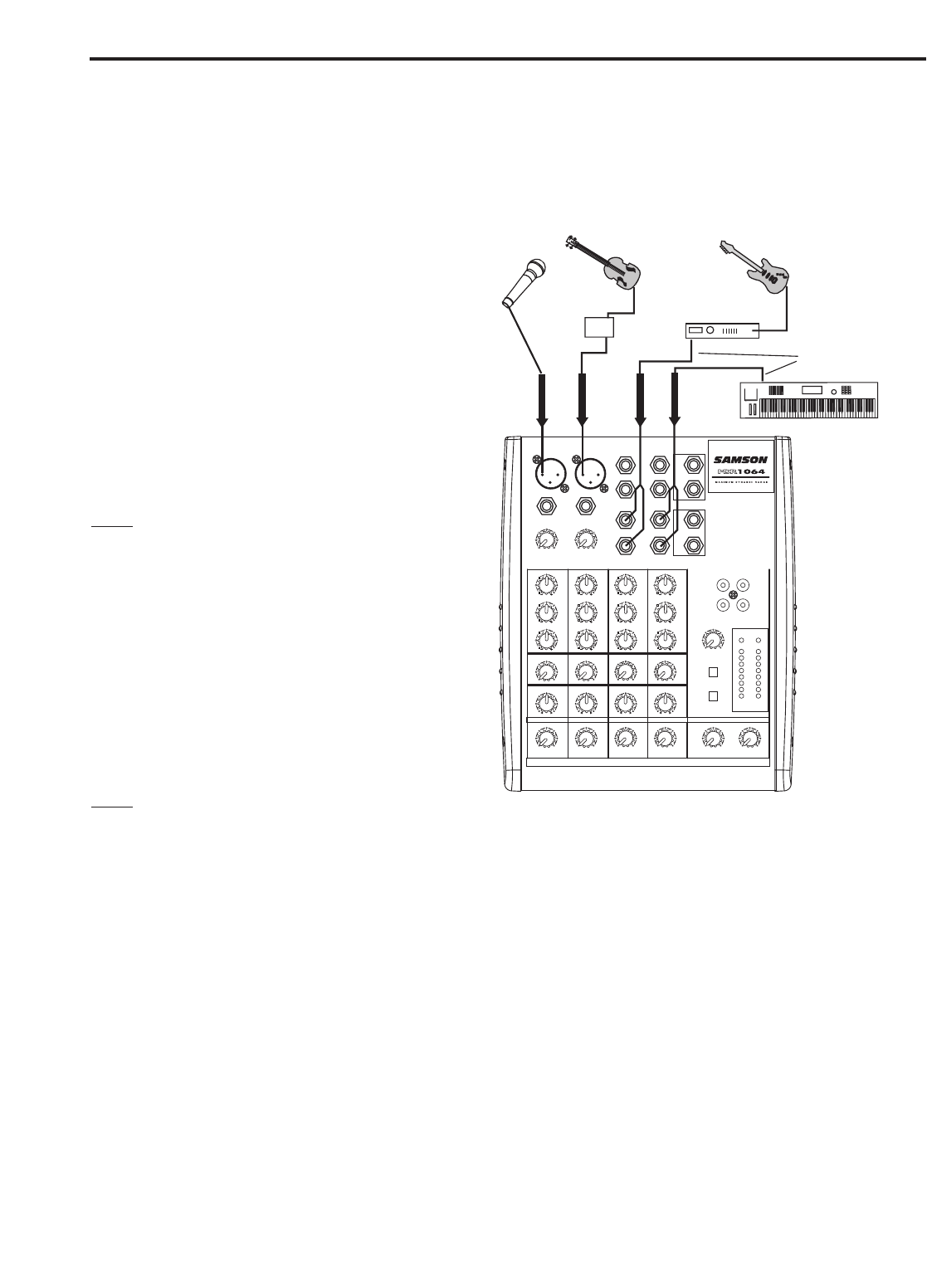
CONNECTING MICROPHONES AND
INSTRUMENTS
1. Before connecting mics or instruments,
make sure that the power of all your sys-
tems components, including the MDR624,
are turned off. Also, make sure that the
Left and Right MIX faders are turned all
the way down.
2. Connect the cables to your microphones
and instruments, and insert the other end
of the cable firmly into the appropriate
input on the MDR624.
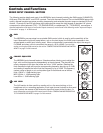
NOTE
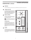
: SETTING THE INPUT GAIN - When
connecting a microphone to channels 1 + 2,
it’s a good idea to start with the Gain Control
turned all the way down. Set the input fader
to the "2 o’clock" position and slowly raise
the GAIN control until you see the CLIP LED
turn on. Now, back the GAIN control down
so that the CLIP LED only lights for a short
time during the loudest input the channel will
see.
3. Switch on the power of any peripheral
devices, and then power up the MDR624.
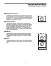
NOTE
: It is important to remember the
Golden Rule of audio … " LAST ON, FIRST OFF". Translated, this means that when turning on your system, you
should always turn your power amplifiers or powered monitors on LAST, and when turning your system off, turn
your power amps off FIRST. This helps avoid any loud pops caused by inrush current at power up, which can
sometimes damage loudspeakers.
4. Turn on your power amp or powered monitors and raise the level control to the manufacturers’ recommend-
ed operating level.
5. Set the Main Level fader in the MDR624’s master section to the "2 o’clock" position.
6. While speaking into the mic (or playing the instrument), adjust the channel Level control so that the "0" LED
of the MAIN section peak level meter lights occasionally.
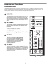
7. You can shape the tone of each channel by adjusting the equalizer controls as desired.
HF
12K
0
15
1010
55
15
MF
2.5K
15
1010
5
15
0
5
0
LF
80Hz
0
15
1010
5
15
5
AUX
010
PAN
0
L
R
0
LEVEL
010
HF
12K
0
15
1010
55
15
MF
2.5K
15
1010
5
15
0
5
0
LF
80Hz
0
15
1010
5
15
5
AUX
010
HF
12K
0
15
1010
55
15
MF
2.5K
15
1010
5
15
0
5
0
LF
80Hz
0
15
1010
5
15
5
AUX
010
HF
12K
0
15
1010
55
15
MF
2.5K
15
1010
5
15
0
5
0
LF
80Hz
0
15
1010
5
15
5
AUX
010
PAN
0
L
R
0
BAL
0
L
R
0
BAL
0
L
R
0
55
LEVEL
010
LEVEL
010
55
LEVEL
010
5
LEVEL
010
5
LEVEL
010
LEFT
RIGHT
LEFT
RIGHT
PHANTOM POWER
CLIP
+12
+6
0
-6
-12
-18
-24
LR
2T IN 2T OUT
AUX RETURN
5
010
2TK TO MIX
2TK TO C/R
OUTPUT LEVEL
30
5
-26
60
+26
GAIN
30
5
-26
60
+26
GAIN
LINE IN LINE IN
LINE IN
MIC IN MIC IN
LINE IN
3/L
4/R
5/L
6/R
AUX RET
LEFT/MONO
RIGHT
AUX SEND
CR OUTPUT
MIX OUTPUT
L
R
L
R
PHONES
CHANNEL 2 CHANNEL 3/4 CHANNEL 5/6 HEADPHONES MAIN LEVELCHANNEL 1
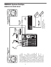
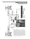
Bass Guitar
Lead Guitar
Keyboards
SIGNAL FLOW
SIGNAL FLOW
S
A
M
S
O
N
R
2
1
SIGNAL FLOW
SIGNAL FLOW
Vocal
Signal Processor
Direct Box
Stereo Signal