


9
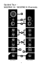
Guided Tour - MIXPAD 12 /
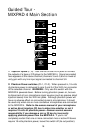
MIXPAD 9 Main Section
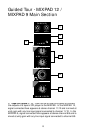
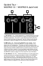
2: Left/Right Peak LEDs (red) - These warning lights indicate an
overload situation. They light whenever the main left or right output
signal is 5 dB short of clipping. To stop them from lighting (and to
eliminate the accompanying sonic distortion), turn down the Main Level
control (see #7 below). See the “Setting the Correct Gain Structure”
section on page 23 in this manual for more information.
3: Power LED - This LED lights steadily red whenever the MIXPAD is
powered on.
4: Power on-off switch - As you may have guessed, this is what you
use to turn the MIXPAD on and off. To avoid potential damage to your
speakers, turn the unit on
before
you turn on any connected power
amps—and turn it off
after
the power amps are turned off.
5: Stereo Auxiliary Return Level (tan) - These knobs determine the
input level of signal arriving via the MIXPAD’s two stereo Auxiliary
returns (1/2 and 3/4). Each return is at unity gain (no boost or attenua-
tion) when set to the “0” (2 o’clock) position. The input signal is boosted
when the knob is turned to the right of “0” and attenuated when turned
to the left of “0.” For information on how to properly set these, see the
sections in this manual entitled “Setting the Correct Gain Structure” and
“Using the Aux Sends and Returns” (pages 23 and 32). Auxiliary return
signal is automatically routed to the Main L/R output.
6: Headphone jack - Connect any standard stereo headphones to this
jack (via a standard 1/4" TRS plug) for private monitoring of the main
stereo output. The built-in MIXPAD headphone preamp delivers
100 mw at 600 ohms.
7: Main Level (white) - This knob determines the final output signal
level—you can think of this as being the “master fader.” Signals from all
channels and Auxiliary returns, as well as the Tape/CD input are routed
here just before leaving the MIXPAD via its left and right main output
jacks. The “0” position of the knob indicates unity gain (no level attenu-
ation or boost). Moving the knob counterclockwise from the “0” position
causes the signal to be attenuated (at the very bottom, it is attenuated
infinitely—in other words, there is no sound). Moving it clockwise from
the “0” position causes the signal to be boosted by as much as 10 dB.
For more information, see the “Setting The Correct Gain Structure”
section on page 23 in this manual.