


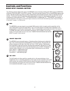
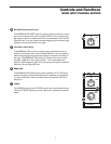
Microphone Input - Mono Input
Channels
Use these inputs to connect Low Impedance
microphones and low level signals from direct
boxes. The MIC inputs have a nominal operating
level of –50dB through -20dB. The MIC inputs
also feature +48V phantom power, allowing you
to use condenser microphones. The Phantom
Power switch (located on the MDR624’s rear
panel) enables phantom power on all the micro-
phone inputs when set to the ON position. XLR
Connector pin-out - Pin 1: Ground, Pin 2: Hot (+),
Pin 3: Cold (-)
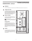
Line Level Input - Mono Input Channels
Use these inputs to connect synthesizers, drum machines, effects processors or any line-level signal.
The LINE inputs have a nominal operating level of -40dB through - 10dB. TRS phone jacks Connector
pin-out - Sleeve: Ground, Tip: Hot (+), Ring: Cold (-)
Line Level Input - Stereo Input Channels
You can connect the outputs from stereo devices such as synthesizers, drum machines, effects proces-
sors or any stereo line-level signal. Use the LEFT input when connecting a mono input signal to the
Stereo Input channels. The LINE inputs have a nominal operating level of -40dB through - 10dB. TRS
phone jacks Connector pin-out - Sleeve: Ground, Tip: Hot (+), Ring: Cold (-)
10
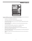
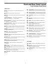
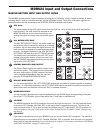
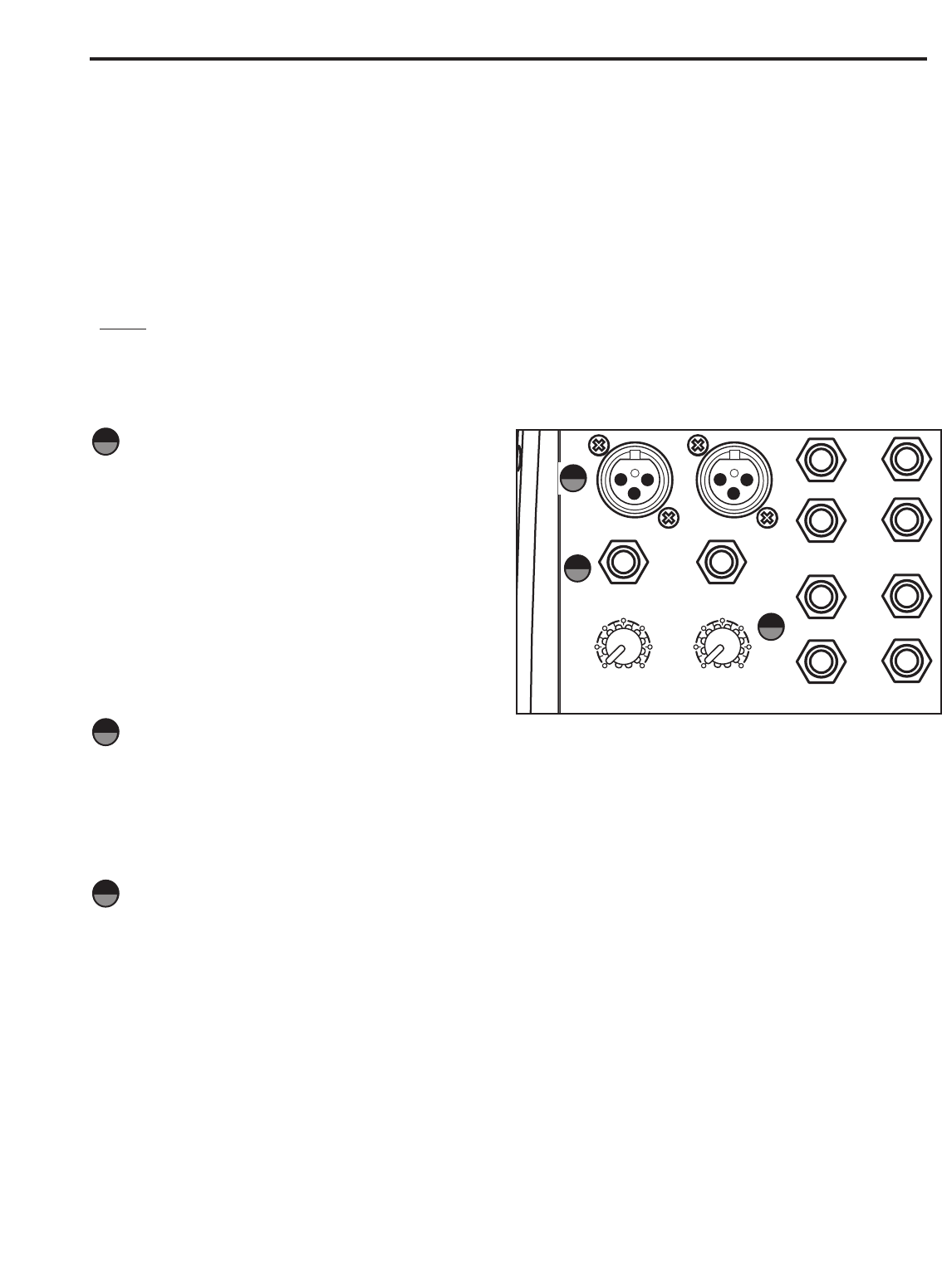
MDR624 Input and Output Connections
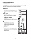
CHANNEL 1 – 6 MIC and LINE INPUTS
The MDR624’s channels 1 and 2 mono input channels each have a 1/4-inch connector for line level inputs and
XLR connectors for the MIC inputs. Channels 3/4 and 5/6 stereo input channels each have 1/4-inch connectors
for line level inputs. By using the GAIN control on channels 1 + 2, you can connect a variety of signal sources
from microphones to line level devices such as synthesizers, and drum machines. All the LINE and MIC inputs
are balanced. The MIC inputs are compatible with microphones with output impedances of 50~600 Ohms and
the LINE inputs are compatible with line level devices of 600 Ohms.
NOTE:
It is not possible to simultaneously use both the LINE and MIC inputs on the same channel. Use only one
of the inputs for the appropriate source on each channel.
Following below is a detailed description of the MDR624’s input and output connectors.
18
30
5
-26
60
+26
GAIN
30
5
-26
60
+26
GAIN
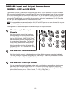
LINE IN LINE IN
LINE IN
MIC
IN MIC
IN
LINE IN
3/L
4/R
5/L
6/R
AUX
RET
LEFT/MONO
RIGHT
AUX
SEND
PHONES
16
17
18
16
17