


DIRECTIONALSTUDIO
MICROPHONEMKH816TU-3
response. The source impedance 01the Senn heiser condenser
microphones with A-B powering is so low (approx. 8 Q at 1000 Hz)
that an amplilier input with an impedance 01at least 400 Q will be
suitable. This is usual in the majority 01cases. However, il the Input
impedance is smaller than 400 Q, a reslstor 01appropriate
value should be placed in series with the microphone so that it
"sees" aleast 400 Q. The voltage division caused by this series
resistor must 01course be consldered. The same method can be
used when a highter output impedance 01the microphone is
demanded. In this case again aseries resistor can be used to
provide correct matching.
Senn heiser condenser microphones produce relatively large output
voltages; these can be up to 1volt with maximum sound pressure
levels. This has the advantage that even with long cables induced
interference signals can be disregarded. Also the internat noise
produced by the microphone does not contribute to the total noise
level. The microphones are litted with high Irequency lilters, wh ich
ensure that no high Irequency signals Irom the microphone can
allect the external circuitry, and also that the microphone Itsell is
protected Irom high Irequency disturbance. It is,therelore, not
necessary, even under the most dillicult conditions, to take special
precautions such as double screening 01the cables or the provision
01high Irequency lilters.
Sennheiser condenser microphones are polarised according to
DIN standard, i. e. when apressure signal strikes the capsule Irom
the lront pin 2 01the XLR-connector goes positive with relerence
to pin 3.
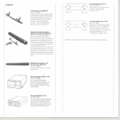
Delivery: 1 microphone
General Description
The directional studio microphone MKH 816 T is a transistorized RF
condenser microphone. The DC voltage necessary lor operation IS
led through the conductors 01the connecting cable (A-B powering
according to the German standard DIN 45595).
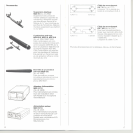
Features:
. High directionality
. Lowequivalent sound pressure level
. Rugged and extremely resistantto unlavourable climatic
conditions
. High sensitivity
. All metal housing with black linish
Principle of high frequency circuit
The capsule 01an RF condenser microphone presents, contrary 10
low Irequency circuits, a low impedance output. Instead 01the high
polarization voltage normally required, a high Irequency capsule
needs only a high Irequency voltage 01about 10 volts, wh ich is pro-
duced bya built-in low noise oscillator (8 MHz). The low capsule
impedance leads to a high performance reliability 01the mlcropho-
nes.
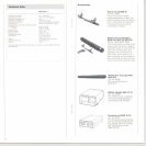
Connection to balanced microphone inputs
In this case the microphone is simply connected to the input 01an
amplilier via a battery adapter MZA 16 TU or the power supply unit
MZN 14 TU.
Powering and connection
Sennheiser electronic introduced A-B powering, which was then
standardized in DIN 45595. As with dynamic microphones, only
two wires are required to connect the microphone when this
powering system is being used. The operating current is led along
the same wires as the audio Irequency signal, so that the circuitry in
the microphone does not have to be connected to earth. Because
01this earth Iree technique the highest possible values 01immunity
lrom noise or disturbance are achieved. For suitable powering units
see "Accessories".
The connection 01Senn heiser condenser microphones and
dynamic microphones as weil is carried out using the prlnciple 01
voltage matching. The advantages 01this system are that neither
impedance variations 01the microphone output nor 01the amplilier
input exercise a noticeable inlluence on the total Irequency
Connection to unbalanced microphone inputs
For connection to unbalanced inputs contact 3 01the connecting
cable between the powering unit and microphone has to be
grounded. Note: With the MZN 16 TU this is only possible after the
unit has been modilied.
Apart Irom cases where the microphone is being used lor proles-
slonal studio purposes, thls ISnot critical, as the large output voltage
01the mlcrophone combined with its low output impedance pro-
vides a large signal to noise ratio. Care should be taken, however,
that no multiple ground circults are lormed when the microphones
are mounted on tripods etc.
Connection to microphone inputs with high sensitivity
IIthe unit being used has a very high Input sensitivlty, i.e. when it IS
normally intended lor use with dynamic microphones, it can be
necessary to reduce the output voltage Irom the microphone by
means 01a voltage divider, which should be built into the micro-
phone cable at the mlcrophone input. By this means the large signal
on the microphone cable is maintained up to Just belore the micro-
phone Input, which results in a Increased signal to noise ratio.
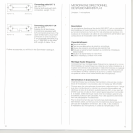
Connection to mixers and sound recording equipment with
powering facilities
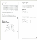
II an approprlate voltage source is available the condenser micro-
phone can be powered directly. The voltage should be 12volts
:t 2 volt. Itshould be so stabilised and filtered, that the unweighted
noise voltage is less than 5 {lV and that the weighted noise compo-
nents are less than 2 {lv. The current consumption 01the micro-
phone is approximately 6 mA. According to the DIN standard the
resistors should be 2 x 180 Q. This means that the voltage drop
across the resistors is appprox. 2 V (Iig. 3).
8
9