


9
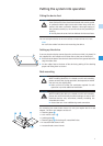
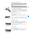
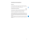
Connecting the optical microphone
̈ Before connecting the optical microphone, remove the protections caps
from the microphone connections 1 and 2 of the central unit. Keep the
protection caps in a safe place for reuse during transport or storage. They
protect the microphone connections against dirt.
̈ Connect the duplex connector ¹ of the optical microphone to the micro-
phone connections 1 and 2 of the central unit. Please observe the
correct insertion direction of the connector. The duplex connector is
connected the correct way round when the label on the connector is facing
downwards as shown.
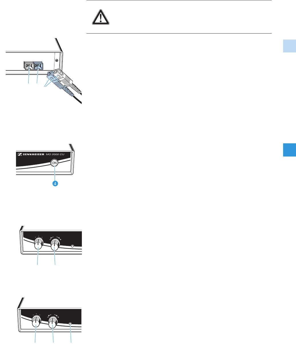
Switching the central unit on/off
After connection to the mains, the device switches on automatically and the
ON button ᕤ lights up.
̈ Press the ON button ᕤ to switch the MO 2000 CU central unit on or off.
Note:
If the power supply is interrupted for several seconds (e.g. due to a power
failure), the device switches on automatically even if it was switched off
before.
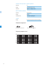
Adjusting the sensitivity
With the microphone connected and both the gain switch ᕡ and the level
control ᕢ set to 0 dB, the specified sensitivity (mV/Pa) is obtained.
̈ Use the gain switch ᕡ to increase the output voltage level by 20 dB
(tenfold increase) or 40 dB (hundredfold increase).
̈ Use the level control ᕢ to steplessly adjust the output voltage level
between –15 dB and +15 dB.
Overload indication
The OVERLOAD LED » indicates both positive and negative voltage peaks.
If the OVERLOAD LED » lights up:
̈ Use the gain control ᕡ and/or the level control ᕢ to reduce the output
voltage level so that the OVERLOAD LED » no longer lights up.
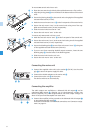
Risk of damage to fiber optic cable!
Fiber optic cable must not be bent like conventional cable!
̈ When installing fiber optic cable, make sure not to bend it
beyond a bend radius of 50 mm.
CAUTION!
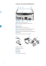
OPTICAL MIC
INPUT
¹
12
LEVEL
OVERLOAD
0
0
40
20
+/- 15dB
dB
GAIN
³ ·
LEVEL
OVERLOAD
0
0
40
20
+/- 15dB
dB
GAIN
³ · »