


()
0
7
more receivers to be operated in the
diversity mode.
Since it is highly unlikely that field
strength minima will occur simultane-
ously at two different antenna sites,
the antennae of the two receivers
should be located at a distance of
several yards from each other. The two
receivers must be connected to each
other, the cables provided for diversity
operation being inserted into the 'diver-
sity' sockets. The equipment connected
to the 'output' socket of only one recei-
ver will then automatically be fed by
this receiver, or by both receivers in
common, when both receive a suffi-
ciently high antenna voltage.
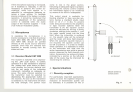
For this application, it is recommended
that a folded dipole be prepared from
240-ohm TV antenna cable. This is done
as indicated in Fig. 11. A 12 foot long
antenna cable is shorted at both ends.
Then, one of the two conductors is cut
in the center and connected with the
conductors of a lead-in cable of any
desired length. The folded dipole thus
obtained must be connected to the
antenna socket on the front of the
receiver marked '240 ohm'. The actual
dipole section (12 feet long) should
then be vertically oriented.
4.2 License
The purchaser of this equipment is
responsible for obtaining the license to
operate it from the appropriate autho-
rities.
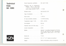
4.3 Special frequencies
While the standard carrier frequencies
are set to 36.7 and 37.1 MHz, the
system can also be supplied with any
two frequencies between 25 and 45 MHz,
(with a frequency spacing of 0.3 to
0.5 MHz), as an optional extra.
4.4 Tape recording
A changeovercontact operated by the
squelchcircuit of the receiveris acces-
sible at the 'auxiliary contact' socket.
This changeover contact enables the
transports of tape recorders to be
operated by electrical remote control
- both by means of the NC and NO
contacts - so that they start when the
transmitter is switched on and stop
with it is switched off. The circuitry of
this contact arrangement can be seen
from the diagram located on the rear
panel of the receiver.
4.5 Powering external units
A OC voltage of 4 V, at a maximum
current of 30 mA, is available at con-
tact 4 of the terminal mentioned in
Section 4.4, for powering external units.
4.6 2 mV output
If the amplifier or tape recorder used
with the receiver does not have a 1.55 V
input, an additional balanced, ungroun-
ded output voltage of 2 mV, with a
source impedance of 10 ohm, is avai-
lable at the contacts 2 and 4 of the
'output' socket. This output can be
connected to the low impedance, baian-
ced microphone input of an amplifier.
4.7 Hum
Since the receiver is already connected
to ground via the ground contact of
the AC power plug, it is essential to
prevent ground loops when subsequent
amplifiers or tape recorders are con-
nected. Regardless of whether the
subsequent amplifier has a balanced
or an unbalanced input, the shielding
of the amplifier cable must be conti-
nued to the contact on the amplifier
housing. On the receiver side, the
screening shielding should remain un-
connected and must, therefore, be kept
from touching contact 2 of the standard
plug.
If, on the other hand, the grounded
plug is replaced by a standard plug
which does not automatically ground
the equipment, it will be necessary for
the receiver housing to be directly
grounded via aseparate line, or con-
nected via the cable shielding, to the
amplifier ground connection. In this
case, the shielding of the cable must
be connected to contact 2 of the stan-
dard plug on the receiver side.