


A.
Using the microphone as supplied, the grip-to-
talk switch operates both the microphone circuit
and an external relay or control circuit. Connect
all leads to the proper terminals of the equip-
ment. (See equipment manual). By using the
white and shield
leads (microphone circuit) or by
connecting the shield and black leads together
and connecting to the proper terminals, the grip-
to-talk switch will operate the microphone circuit
but the external relay or control circuit is not
operated, and the microphone can be
VOX
operated with the microphone being muted by
the switch.
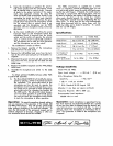
B.
By the minor modification of cutting the green
lead (see Figure
A
and instructions below) the
microphone circuit
is
removed from the switch
action and the switch will operate the external
relay or control circuit in push-to-talk operation.
The microphone can be used for VOX operation
and the microphone can not be muted.
The modification is made as follows:
I.
Remove the integral assembly of the microphone
and switch from the desk stand.
2.
Remove the 4-40 phillips head screw from the bot-
tom of the switch case and pull out the bakelite re-
ceptacle.
3.
Disconnect the green wire from pin
#3,
insulate the
bare end of the wire, and put the wire back into the
switch case.
4.
Replace the bakelite receptacle and the 4-40
phillips
head screw.
5. Assemble the microphone and switch to the desk
stand.
To obtain optimum flexibility between either VOX
or push-to-talk operation.
The Shure Model
A87K Kit will modify the micro-
phone by placing a switch in the black lead from
the receptacle. The grip-to-talk switch of the
micro~hone can then be used to o~erate the
microbhone circuit and the external day or con-
trol circuit can be operated or NOT operated by
grip-to-talk switch
by
changing the position of
the
A87K switch. This will permit instant change-
over from VOX operation to push-to-talk opera-
tion and
still
retain the microphone circuit switch
to mute the microphone in either operation.
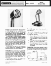
Operation:
No special precautions beyond ordinary
care are necessary in the operation of the Models 440
and
440SL Microphones. They will operate satisfactorily
under ordinary conditions in hot and cold climates. To
retain the full strength of the permanent magnet and to
maintain alignment of structure, dropping or other se-
vere mechanical shocks should be avoided.
The
440SL microphone, as supplied, has a switch
which
is
a momentary contact non-locking) ty e. For use
I
K
as a grip-to-talk switch, grasp
t
e switch with and press-
ing the bar with fingers.
If
desired, the switch may be
converted to a grip-to-talk, slide-to-lock switch. This may
be done by loosening the number 5-40
Philli
s Head ma-
g
chine screw, directly beneath the switch ar, rotating
the "Stop-Plate" one-half turn and retightening the ma-
chine screw. To lock, press the bar and simultaneously
apply force downward with the index finger until the
switch bar slides and
is
locked in position. To unlock,
slide bar up with fingers.
Specifications:
Voltage Sensitivity
Height Overall
Length Overall
Width Overall
Finish
Net Weight
with
7'
(2.ln-t) Cable
Shpg. Weight
with
7'
(2.lm) Cable
Model 440 and 440SL
Open circuit voltage
.........
-
52.5
db
':
(2.38 mv)
E.I.A.
Microphone Rating
GM
.!.
-7,
............................
Sensitivity
-
142.3 db,*-.
MODEL 440
2s (61.lmm) Dia.
3%" (82.6mm)
2s (61.lmm) Dia.
Gray and Chrome
3/4
Ib. (340g)
Ifi
Ibs. (6809)
*
odb
=
I
volt per microbar
'8"
E.I.A.
Standard SE-105 August 1949
MODEL 440SL
9%"
(238.lmm)
7"
(177.8mm)
5"
(127rnm)
Gray and Chrome
2v2 Ibs.
(1
134g)
5
Ibs. (2722g)
Microbar
=
one dyne per square centimeter
Frequency Response: 300 to 3000
c.p.s.
Recommended Load Impedance:
100,000 ohms or more
Guarantee:
Each micro hone is guaranteed
to
be
free from electrical and
mec
K
anical defects for a period
of one year from date of shipment from the factory, pro-
vided all instructions are complied with fully. In case of
damage, return the microphone to the
fadory for re-
pairs. Our guarantee
is
voided
if
the microphone case
is opened.