


2
9Vdc
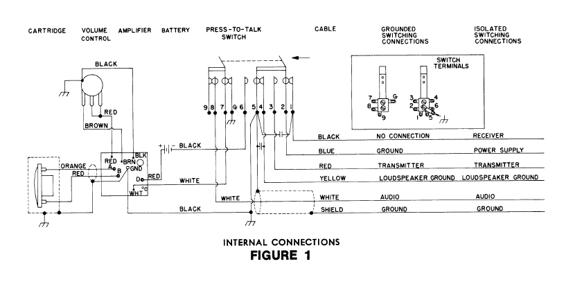
The general wiring procedure for tranceiver connections
is as follows:
Microphone Audio Input Circuit:
1. Connect the WHITE cable lead to the microphone au-
dio input terminal.
2. Connect the SHIELD to chassis or circuit ground of
the transceiver (see Guide and CAUTION
below).
Electronic or Relay Switching Circuit:
GROUNDED SWITCHING
Most transceivers employ a grounded circuit to switch
from the receive to the transmit position. To connect the mi-
crophone to such a circuit, proceed as follows:
1. At the end of the cable, connect the RED lead to the
terminal used to complete the transmitter circuit.
2. Connect the BLUE lead to chassis or circuit ground of
the transceiver (see Guide and CAUTION below).
3. Connect the YELLOW lead to the terminal used to
complete the receiver circuit. This will usually be a
ground return from the loudspeaker circuit. If a micro-
phone switching contact is not required for loudspeak-
er ground, insulate (wrap with tape) the YELLOW
lead.
4. The BLACK lead is usually not used; insulate the
BLACK lead. However, if both a receiver ground and a
loudspeaker ground are required, connect the YEL-
LOW lead to loudspeaker ground, and the BLACK
lead to the receiver ground.
ISOLATED SWITCHING
In some transceivers, an isolated circuit is required to
switch power supply voltages rather than grounds. If an iso-
lated switching circuit is required, proceed as follows:
1. At the end of the cable, connect the RED lead to the
isolated switch contact terminal used to complete the
transmitter circuit.
2. Connect the BLUE lead to the terminal used for the
switched power supply.
3. Connect the BLACK lead to the terminal used to com-
plete the receiver circuit. If the power supply is not
switched to the receiver circuit by a microphone
switching contact, insulate (wrap with tape) the
BLACK lead.
4. Connect the YELLOW lead to the loudspeaker ground
return. If a microphone switching contact is not re-
quired for the loudspeaker ground, insulate the YEL-
LOW cable lead.
CAUTION
Make certain that the SHIELD and/or the BLUE lead are
not connected to chassis ground for those models where the
Guide specifies they should be connected to circuit ground.
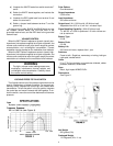
SPECIAL SWITCHING
In some transceivers, special switching circuits are re-
quired. Three types are described below. In all of the types,
before making the required circuit alterations, remove the
microphone baseplate by unscrewing the two screws secur-
ing it.
1. If a grounded audio input is required in the receive
mode, solder a jumper lead between switch terminal 9
and the ground lug (see Figure 1).
2. If both and isolated and grounded transmit circuit are
required, along with a grounded receive circuit (see
Figure 1):
a) Unsolder the WHITE leads from switch terminals 7
and 8.
b) Solder the WHITE leads together, and insulate the
connection.
c) Cut the BLACK cable lead from terminal 1 and sol-
der it to terminal 8.
d) Solder a jumper lead between terminal 7 and the
ground lug.
At the end of the cable, the BLUE and RED leads are now
the isolated transmit leads; the BLACK lead is the grounded
transmit lead; and the YELLOW lead is the grounded receive
lead.
3. If both an isolated and grounded receive circuit are
required, along with a grounded transmit circuit (see
Figure 1):