


2
Polarity
Positive pressure on diaphragm produces positive volt-
age on pin 2 (with respect to pin 3). See Figure 4.
Switch
Built-in magnetic reed on/off switch with lockplate. To
lock switch in th ON position, remove screw on lockplate
and turn lockplate 180_. Reassemble and tighten screw.
Cartridge Shock Mount
lnternal rubber vibration-isolator
Swivel Adapter
Positive action, adjustable through 90_ from vertical to
horizontal, permits easy removal for handheld use, suit-
able for mounting on stand with
5
/
8
”–27 thread
Case
Chrome-plated die casting with ARMO-DUR
grille and
stainless steel screen
Dimensions
See Figure 5
Net Weight (less cable)
255 grams (9 oz)
CERTIFICATIONS
Conforms to European Union directives, eligible to bear
CE marking; meets European Union EMC Immunity Require-
ments (EN 50082–1: 1992).
FURNISHED ACCESSORY
Swivel Adapter A25D. . . . . . . . . . . . . . . . . . . . . . . . . . . . . . . .
REPLACEMENT PARTS
Cartridge R45. . . . . . . . . . . . . . . . . . . . . . . . . . . . . . . . . . . . . . . .
Plug Element RK169P. . . . . . . . . . . . . . . . . . . . . . . . . . . . . . . .
Screen and Grille RK244G. . . . . . . . . . . . . . . . . . . . . . . . . . . . .
OPTIONAL ACCESSORIES
Line Matching Transformer A95 Series. . . . . . . . . . . . . . . . . .
Desk Stand S37A, S39A. . . . . . . . . . . . . . . . . . . . . . . . . . . . . .
Isolation Mount A55M. . . . . . . . . . . . . . . . . . . . . . . . . . . . . . . .
Dual Mount A26M. . . . . . . . . . . . . . . . . . . . . . . . . . . . . . . . . . . .
Windscreen A2WS. . . . . . . . . . . . . . . . . . . . . . . . . . . . . . . . . . .
Cable, LO–Z (7.6 m [25 ft]) C25J. . . . . . . . . . . . . . . . . . . . . . .
Cable, HI-Z (6.1 m [20 ft]) C20HZ. . . . . . . . . . . . . . . . . . . . . .
ARCHITECTS’ SPECIFICATIONS
The microphone shall be a moving coil (dynamic) type with
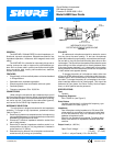
a frequency response of 50 to 15,000 Hz. The unit shall have
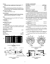
a cardioid polar characteristic. The cancellation at the sides
shall be approximately 6 dB, and the cancellation at the rear
shall be 15 to 20 dB. The microphone shall be dual impedance
with a rated impedance of 150 ohms for connection to micro-
phone inputs rated at 19 to 300 ohms and “High” for connection
to high–impedance microphone inputs. lmpedance change
shall be solderless at the microphone connector.
The microphone output shall be:
Low lmpedance –58.0 dB. . . . . . . . . . . . . . . . . . . . . . . . . . . . .
(0 dB = 1 volt per Pascal)
High lmpedance –35.0 dB. . . . . . . . . . . . . . . . . . . . . . . . . . . . .
(0 dB = 1 volt per Pascal)
The microphone shall have an XLR, three–pin profession-
al audio connector and shall be equipped with a magnetic reed
On–Off switch.
The microphone shall be provided with a swivel adapter,
adjustable through 90_ from vertical to horizontal, and suitable
for mounting on a stand having a
5
/
8
”–27 thread.
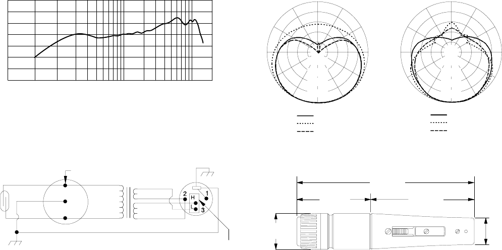
The overall dimensions of the microphone shall be 157
mm (6–
3
/
16
in.) in length and 31.9 mm (1
1
/
4
in.) in diameter.
The microphone shall be the Shure Model 545SD-LC or
equivalent.
20 200001000 1000050 100
98765432
98765432
+10
0
–10
Hz
dB
TYPICAL FREQUENCY RESPONSE
FIGURE 2
150
o
120
o
150
o
120
o
180
o
30
o
60
o
90
o
30
o
60
o
90
o
–5 dB
–10 dB
–15 dB
–20 dB
0
150
o
120
o
150
o
120
o
180
o
30
o
60
o
90
o
30
o
60
o
90
o
–5 dB
–10 dB
–15 dB
–20 dB
0
125 Hz
500 Hz
1000 Hz
2000 Hz
4000 Hz
8000 Hz
TYPICAL POLAR PATTERNS
FIGURE 3
CARTRIDGE TRANSFORMER XLR CONNECTOR
CODED TERMINAL
IMPEDANCE SELECTION SOCKET
(SHOWN IN LOW IMPEDANCE POSITION)
REED
SWITCH
GREEN
BLACK
YELLOW
GREEN
YELLOW
BLACK
RED
BLUE
WHITE
BLACK
INTERNAL CONNECTIONS
FIGURE 4
(1 1/4 in.)
32 mm
157 mm
(6 3/16 in.)
23 mm
(15/16 in.)
64 mm
(2 1/2 in.)
93 mm
(3 11/16 in.)
OVERALL DIMENSIONS
FIGURE 5