


2
Impedance
Microphone rating impedance is 150 ohms (270 ohm
actual) for connection to microphone inputs rated at 75
to 300 ohms
Output Level (at 1,000 Hz)
Open Circuit Voltage –78.0 dB (0.13 mV). . . . . . . . . . .
0 dB = 1 volt per microbar
Power Level –58.5 dB. . . . . . . . . . . . . . . . . . . . . . . . . . . . .
0 dB = 1 milliwatt per 10 microbar
Polarity
Positive pressure on the diaphragm produces positive
voltage on pin 2 relative to pin 3 of the output connector
Switch
Built–in On/Off switch, integral part of swivel mount
connector Three pin professional type, designed to
mate with Cannon XL series, Switchcraft A3 (Q.G.) se-
ries, or equivalent
Case
Chrome–plated die casting
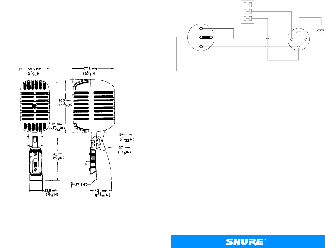
Dimensions
See Figure 3
OVERALL DIMENSIONS
FIGURE 3
Net Weight
625 grams (22 oz)
Certifications
Conforms to European Union directives, eligible to bear
CE marking; meets European Union EMC Immunity
Requirements (EN 50 082–1, 1992).
POLARITY
To test two microphones and their cables for common
polarity, connect them to an amplifier and talk or sing into
them while holding them three or four inches apart. The
sound from the speakers should be the same when talking
into either microphone or directly between them if they have
common polarity. If the sound level drops drastically, or if a
dead spot is found, when talking between the two micro-
phones, either the microphones or their cables have differ-
ent polarity. All cables and microphones can be tested in this
manner to ensure that they have common polarity.
To reverse the polarity of a low–impedance microphone
cable, use either a Shure A15PRS Switchable Phase Re-
verser or interchange the wires connected to pins 2 and 3 of
the connector. To reverse the polarity of a microphone, inter-
change the cartridge leads (see Figure 4.) This should be
performed by your dealer, the Shure Factory Service De-
partment, or other qualified service personnel.
CARTRIDGE
SWITCH
XLR CONNECTOR
BLACK
YELLOW
CODED TERMINAL
BLUE
YELLOW
BLACK
1
2
3
INTERNAL CONNECTIONS
FIGURE 4
OPTIONAL ACCESSORIES
Desk Stand S37A, S39A. . . . . . . . . . . . . . . . . . . . . . . . . . . .
Line Matching Transformer A85F, A95UF. . . . . . . . . . . . . .
Cable and Plug Assembly C25B, C25E, C25J. . . . . . . . . .
REPLACEMENT PARTS
Cartridge R115. . . . . . . . . . . . . . . . . . . . . . . . . . . . . . . . . .
On/Off Switch RK32S. . . . . . . . . . . . . . . . . . . . . . . . . . . . .
Plug Element RK169P. . . . . . . . . . . . . . . . . . . . . . . . . . . .
For additional service or parts information, please con-
tact Shure’s Service department at 1-800-516-2525 or
www.shure.com. Outside the United States, please contact
your authorized Shure Service Center.
The Sound of Professionals...Worldwide
Shure Brothers Incorporated
222 Hartrey Avenue, Evanston IL 60202-3696
Phone: 847 866-2200 FAX: 847 866-2279
In Europe, Phone: 49-7131-72140 FAX: 49-7131-721414
Internationally, Phone: 847 866-2200 FAX: 847 866-2585
Website www.shure.com