


3
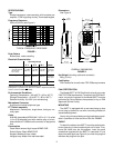
Microphone connector wiring is shown in the table below.
Microphone Connector Wiring
Pin
Color Function Pin Color Function
1 N.C. 5 Black PTT
Switch
Ground
2 White Dc Bias (+),
Audio Out
6 Red Audio Out
(Ac
coupled)
3 Yellow PTT Switch 7 Drain Ground
4 Blue NC 8 N.C.
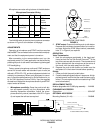
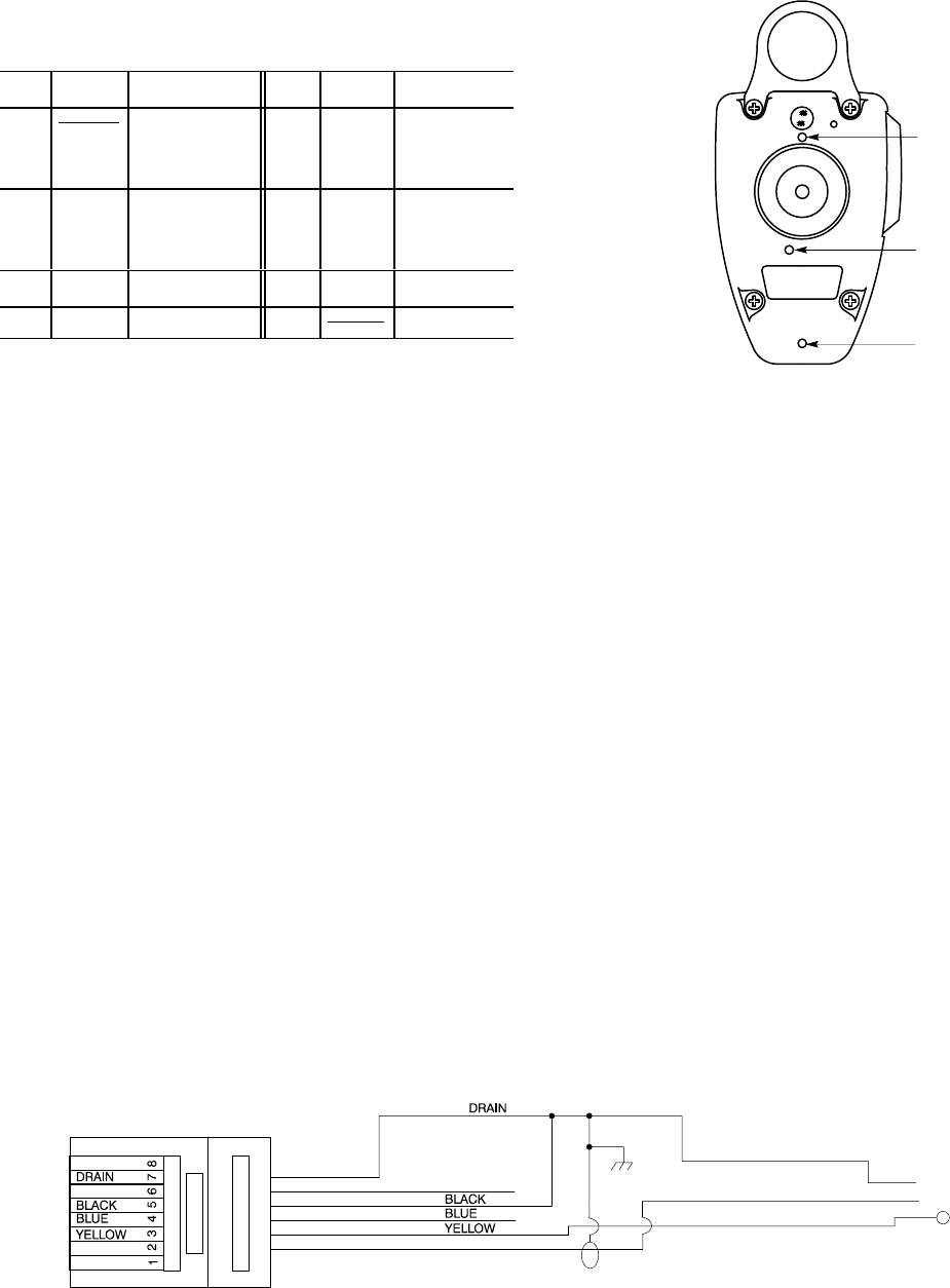
The ALM-88 cable is wired at the microphone connector
as shown in Figure 3 at the bottom of the page.
ADJUSTMENTS
Operation of microphone and DTMF functions requires
that the 888TT be connected to the communications equip-
ment and that the equipment power is turned on.
After connection to the communications set, turn the
equipment power On. Power application can be verified by
pressing the push-to-talk switch and observing the keypad
LED backlighting.
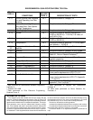
Factory preset microphone audio and DTMF levels are
correct for aircraft radios with standard input circuits (as
defined in RTCA DO-170), and level adjustment should not
ordinarily be necessary. When such adjustment is neces-
sary, it should be performed only by Shure Brothers Inc. or
by an FAA Approved Service Facility. Use the supplied
screwdriver to adjust the microphone sensitivity and DTMF
output levels as follows:
1.
Microphone sensitivity:
Press the push-to-talk but-
ton and speak normally into the microphone while
checking transmitter modulation. Adjust the micro-
phone sensitivity control (case back, hole “B” in Figure
4) and repeat the talk test as required.
DTMF LEVEL
ADJUST (C)
MICROPHONE
SENSITIVITY
ADJUST (B)
CABLE
RELEASE (A)
MICROPHONE CASE BACK
FIGURE 4
2.
DTMF output:
Press and hold the push-to-talk button.
Depress and hold down a keypad button for a continu-
ous tone. Adjust the DTMF output control (case back,
hole “C” in Figure 4) as required.
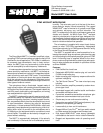
OPERATION
Voice Transmission
1. Hold the microphone comfortably in the hand posi-
tioned so that the Top-Talk Sound Channels
TM
at the
top of the case are near the mouth. The clearest sound
is often obtained with the microphone at the corner of
the mouth, with the cable away from the face.
2. Depress the push-to-talk button and make sure the
equipment is in the transmit mode before speaking.
Dialing
1. Press and hold the push-to-talk button.
2. Press the desired keypad buttons in sequence. A high-
pitched tone will confirm that the code has been trans-
mitted. (The microphone audio is muted during DTMF
tone transmission.)
REPLACEMENT PARTS
Modular plug-cable with PJ-068 plug assembly ALM-88. .
FURNISHED ACCESSORY
Screwdriver 65A1587. . . . . . . . . . . . . . . . . . . . . . . . . . . . . .
OPTIONAL ACCESSORY
Mounting Bracket (3 in kit) RK6MB. . . . . . . . . . . . . . . . . .
TIP (PTT)
SLEEVE (GROUND)
RING (AUDIO)
PJ-068 CONNECTOR (TO RADIO)
RJ11 CONNECTOR (TO MICROPHONE)
NC
NC
RED
WHITE
WHITE
RED
MODULINK CABLE WIRING
FIGURE 3