


24
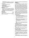
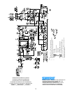
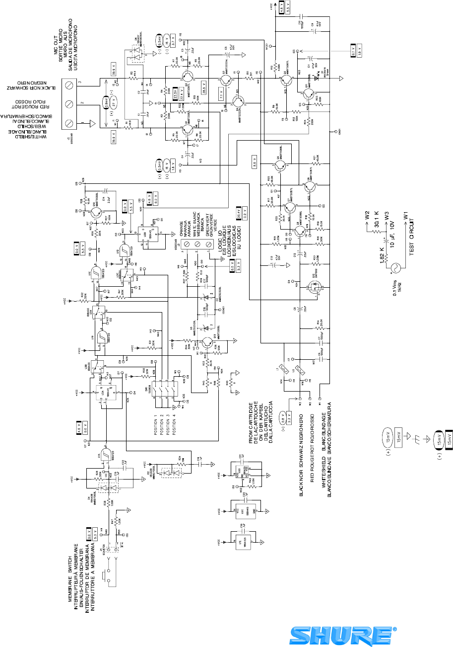
1. All resistors 1/10W, ±1%, 0805, unless o therwise specified.
2. ElectrolyticcapacitorsshowninmFxVolts.Allnon--polarcapacitors
in mF, ±10%, and 50V or moreunless otherwise specified.
3. = AC Voltage
= DC Voltage
= Printed Circuit Ground
= Case Ground
= Logic Ground
= AC Voltage, Mic Muted (J4 Shorted)
= DC Voltage, Mic Muted (J4Shorted)
(+) and/or (--) indicate AC polarity relative toinput test signal.
4. Connect J2 to mic input of aShure M367 Mixer or equivalent, with
48V phantom power switched on.
NOTES;
MX392/MX393 SCHEMATIC DIAGRAM
SCHEMA DE PRINCIPE MX392/MX393
STROMLAUFPLAN FUR MX392/MX393
DIAGRAMA ESQUEMATICO DEL MX392/MX393
SCHEMA CIRCUITALE DEI MODELLI MX392/MX393
FIGURE 1 1 S ABBILDUNG 1 1 S FIGURA 1 1
SHURE Incorporated Web Address: http://www.shure.com
222 Hartrey Avenue, Evanston, IL 60202-3696, U.S.A.
Phone: 847-866-2200 Fax: 847-866-2279
In Europe, Phone: 4 9-7131-72140 Fax: 49-7131-721414
In Asia, Phone: 852-2893-4290 Fax: 852-2893-4055
E
l
sewhere,
P
hone: 84
7
-
866
-
2
2
00 Fax: 84
7
-
866
-
2
5
8
5