


ENGLISH
6
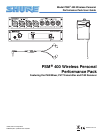
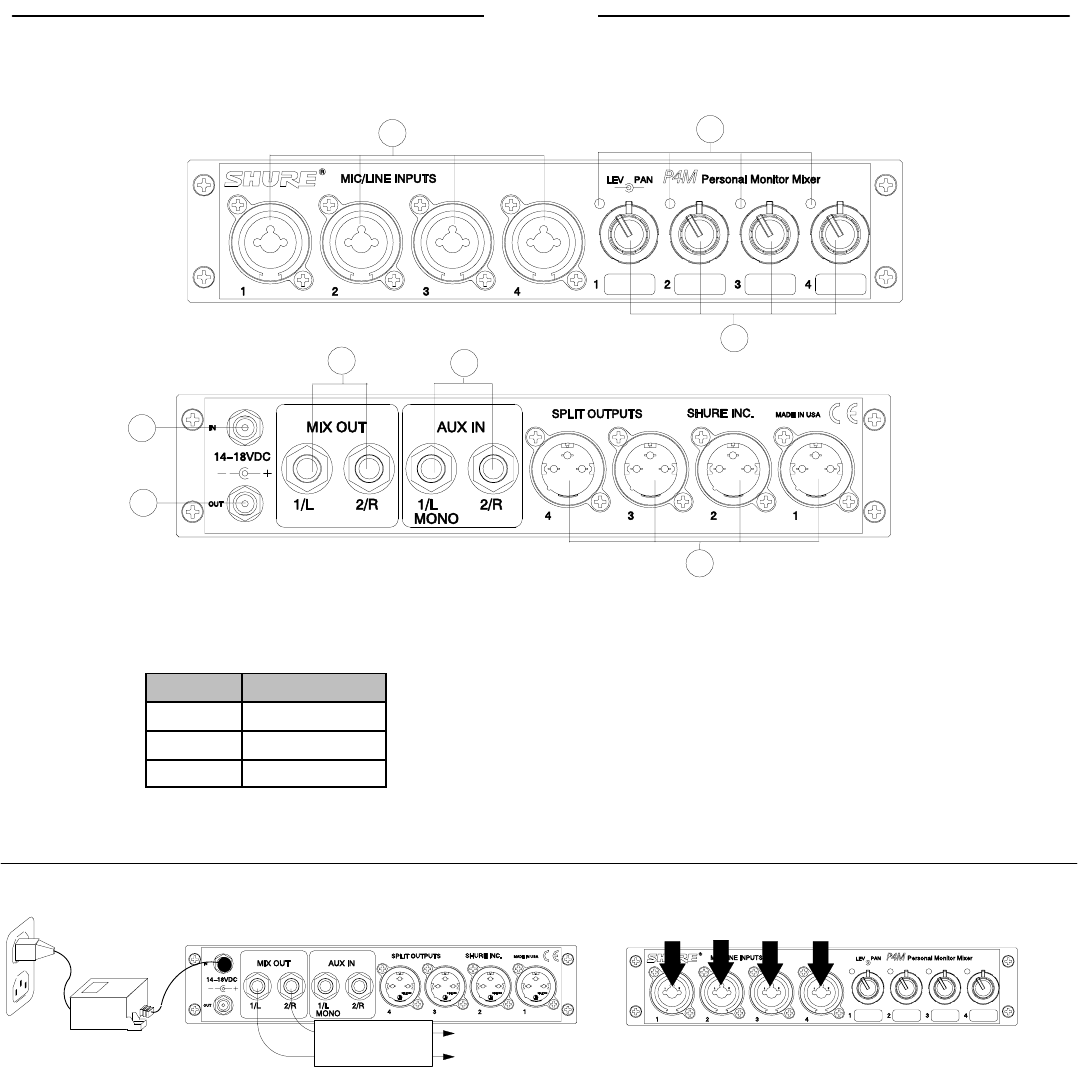
THE P4M MIXER
Controls and Features
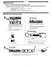
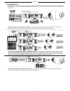
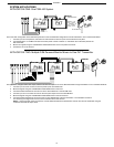
MIXER BACK PANEL
MIXER FRONT PANEL
1
2
3
8
7
6
5
4
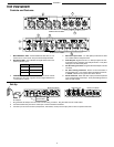
1. MIC/LINE INPUT Jacks: Accommodate both XLR and 1/4” con-
nectors at mic or line levels. They are electronically balanced.
2. Signal/Clip LEDs: Color indicates the signal status of the corre-
sponding mic/line input:
LED Color Signal Status
Green Signal present
Yellow Nominal Level
Red Signal clipping
3. CONCENTRIC LEVEL/PAN Knobs: The inner knob controls
the input level; the outer ring pans the input signal between the
1/L and 2/R mix outputs.
4. MIX OUT Output Jacks: 1/4” TRS jacks provide the line level
mix created with the level/pan knobs.
5. AUX IN Inputs: Signals from two 1/4” TRS input jacks are com-
bined with the mix created by the level/pan knobs. Front panel
settings do not affect these jacks.
6. DC IN Locking Connector: Plug the PS40 AC adaptor into this
connector.
7. DC OUT Locking Connector: Powers a P4T transmitter or
another P4M mixer. A DC jumper cable is provided with the mix-
er. NOTE: A PS40 can only power two Shure devices.
8. SPLIT OUTPUTS: Each male XLR output provides a duplicate
of its corresponding mic/line input. Front panel settings have no
effect on split outputs.
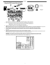
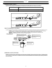
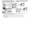
Set-Up
To audio input
of transmitter
PS40
AC Adaptor
Audio Sources
Mixer Back Panel
Mixer Front Panel
1. Plug the PS40 AC adaptor into the mixer’s DC IN locking connector. Plug the other end into a wall socket.
2. Connect the MIX OUT jacks to the audio input of the P4T wireless transmitter.
3. Connect up to four audio sources (microphones, instruments, mixers) into the input jacks on the front panel of the mixer.