1010
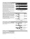
INSERTING A 15 dB MICROPHONE PREAMPLIFIER PAD
Each channel’s microphone preamplifier gain can be reduced
by 15 dB. This may be desirable with extremely high-output mi-
crophones.
Procedure:
To pad the gain of the MIC position
1. Remove surface mount resistor R1023.
2. Solder a 680 : resistor at jumper X112. For a greater gain
reduction, use a resistor with a value greater than 680 :.
Use a lesser value resistor for less reduction.
To pad the gain of the PHM (phantom) position:
1. Remove surface mount resistor R1026.
2. Solder a 1.5 k: resistor at jumper X110. This reduces
gain by 8 dB. For a greater gain reduction, use a resistor
with a value greater than 1.5 k:. Use a lesser value resis-
tor for less reduction.
NOTE To compensate for higher output condenser micro-
phones, the factory set gain in the PHM position is 13 dB lower
than the gain in the MIC position.
LINE-LEVEL OUTPUT TO MIC-LEVEL OUTPUT
Procedure:
1. Short jumper X901.
2. Remove resistors R900 and R909.
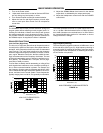
DISABLE MASTER LEVEL CONTROL
The Master gain control can be disabled so it cannot be tam-
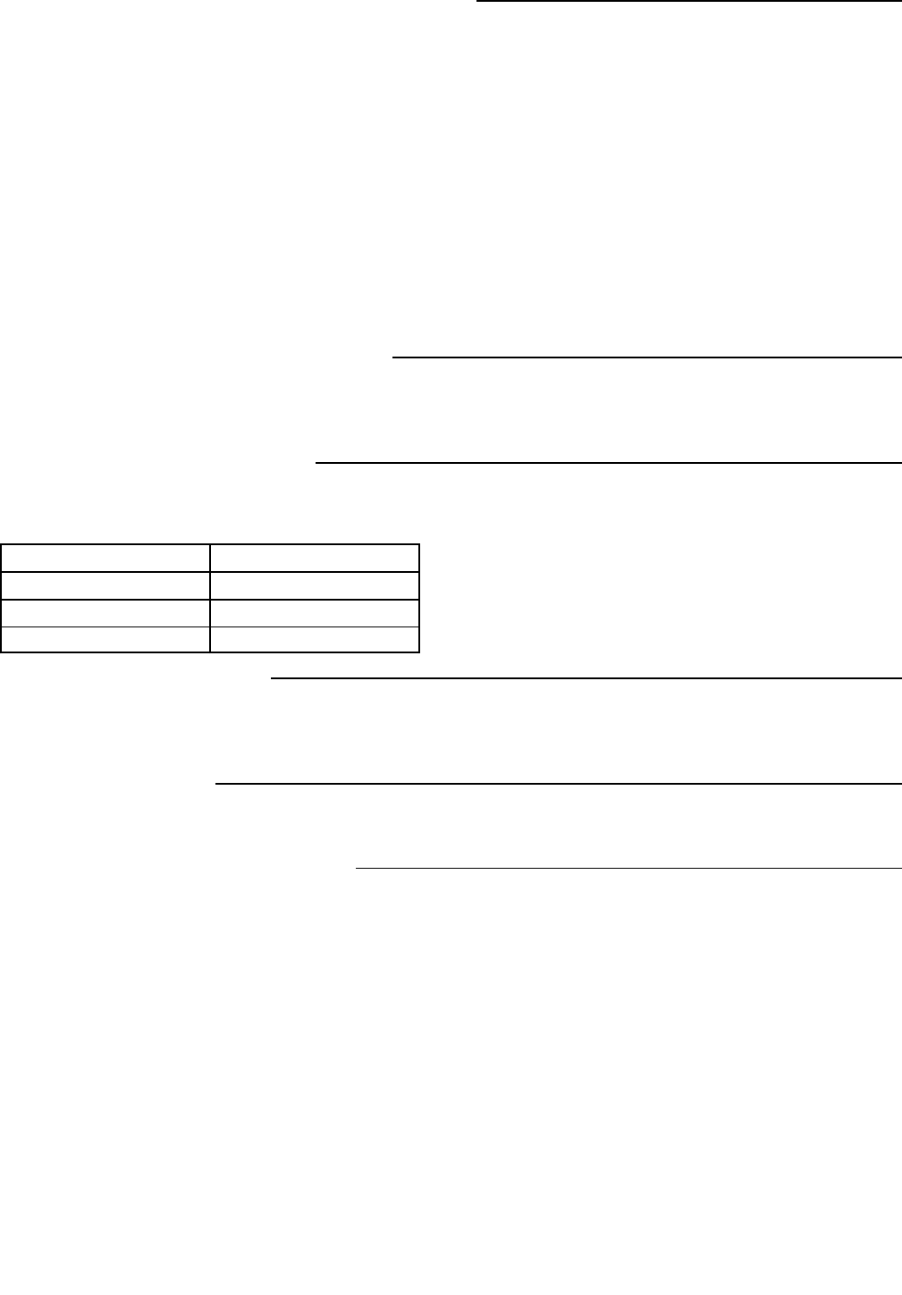
pered with. The following table indicates the resistor value to
be used for the desired gain.
Master Section Gain Resistance
-6 dB 5.1 k:
0 10 k:
6 dB 20 k:
Procedure:
1. Remove resistor R9230.
2. Install new resistor at jumper X914.
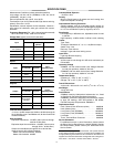
CHANGE LIMITER THRESHOLD
All three threshold settings (+16, +8 and +4 dBm) can be
changed. To shift the threshold down by 6 dB, resistor R will be
82 k:. To shift the limiter thresholds up by 6 dB, R will be 330 k:.
Procedure:
1. Remove resistors R9177 and R9180.
2. Install new resistor R at jumper X907.
LOCAL AUX OPERATION
With linked mixers, the Aux input from a modified mixer does
not link.
Procedure:
Remove resistor R9024.
SEND/RETURN (INSERT) TO DIRECT OUT
Changes a channel’s
1
/
4-
inch insert jack to a Direct Out jack. Procedure:
1. Remove resistors at X101, X102, X105 and X106, and
X808 if modifying channel 8.
2. Short jumpers R1011 and R1020.
SEND/RETURN TO DIRECT OUT POST-FADER
A channel’s Insert phone jack can be changed to Direct Out,
post-fader.
Procedure:
1. Remove resistors at X101, X102 and X105.
2. Short jumpers at R1020.


