


2
SPECIFICATIONS
Type
Dynamic, close-talk
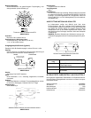
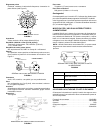
Frequency Response (at 8 mm [5/16 in.])
50 to 15,000 Hz (see Figure 2)
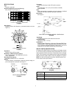
TYPICAL FREQUENCY RESPONSE
FIGURE 2
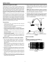
Polar Pattern
Cardioid, uniform with frequency, symmetrical about axis (see
Figure 3)
TYPICAL POLAR PATTERN
FIGURE 3
lmpedance
Rated at 150 Ω (223 Ω actual)
Sensitivity (1,000 Hz at 8 mm (5/16 in.)
Open Circuit Voltage: –65.0 dBV/Pa* (0.45 mV)
*1 Pa = 94 dB SPL
Hum Sensitivity (typical)
35.5 dB equivalent SPL in a 1 mOe field
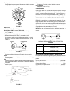
Polarity
Positive pressure on diaphragm produces positive voltage on
pin 2 of microphone connector. See Figure 4.
SM10A WIRING DIAGRAM
FIGURE 4
Connector
Professional three-pin male XLR audio connector.
Cable
Non-detachable, 1.5 m (5 ft), two-conductor, shielded,
plastic-jacketed
Case
Black thermoplastic microphone and pivot housing, anodized
aluminum end caps, stainless steel grille, and boom
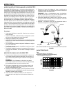
Dimensions
See Figure 5
SM10A AND HEADBAND ASSEMBLY DIMENSIONS
FIGURE 5
Net Weight
78 grams (2.7 ounces) less cable and connector
Packaged Weight
950 grams (2 lbs., 1 1/2 oz)
Certification
Eligible to bear CE Marking. Conforms to European EMC Direc-
tive 89/336/EEC. Meets applicable tests and performance crite-
ria in European Standard EN55103 (1996) parts 1 and 2, for
residential (E1) and light industrial (E2) environments.
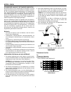
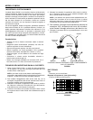
ON-OFF SWITCH MODIFICATION
As supplied, the SM10A does not include an on-off switch. Howev-
er, one can be easily constructed using a Switchcraft T3F 3-pin fe-
male professional audio connector, or equivalent, with an integral
switch. This connector can be attached to the cable connecting the
SM10A to the PA system. Refer to the wiring diagram in Figure 6.
NOTE: In order for the switch to be silent, phantom power must
not be active on this input channel.
ON-OFF SWITCH WIRING DIAGRAM
FIGURE 6
12
3
CARTRIDGE XLR CONNECTOR
RED CODED SIDE
BLK
RED
Reference
Designator
Part Description
J1 3-Pin female audio connector, chassis mount
J2 3-Pin male audio connector, chassis mount
S1 Miniature toggle switch, SPST
1
2
3
1
2
3
S1
J1
INPUT
J2
OUTPUT