


2
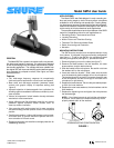
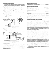
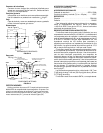
RIGHT SIDE VIEW REAR VIEW
XLR CONNECTOR
MICROPHONE STAND MOUNTING CONFIGURATION
FIGURE 2
SPECIFICATIONS
Type
Dynamic
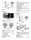
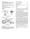
Frequency Response
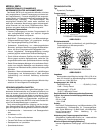
50 to 20,000 Hz (see Figure 3)
FLAT RESPONSE
BASS ROLLOFF
PRESENCE BOOST
TYPICAL FREQUENCY RESPONSE
FIGURE 3
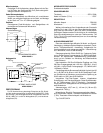
Polar Pattern
Cardioid (unidirectional)–uniform with frequency, sym-
metrical about axis (see Figure 4)
TYPICAL POLAR PATTERNS
FIGURE 4
Impedance
Microphone impedance rating is 150 Ω (150 Ω actual) for
connection to microphone inputs rated at 19 to 300 ohms.
Phasing
Positive pressure on diaphragm produces positive volt-
age on pin 2 relative to pin 3.
Output Level (at 1,000 Hz)
Open Circuit Voltage* – 59.0 dB (1.12 mV)
. . . . . . . . . .
*0 dB = 1 volt per Pascal
Electromagnetic Hum Sensitivity
(Typical, Equivalent SPL/milliOersted)
60 Hz: 11 dB
500 Hz: 24 dB
1 kHz: 33 dB
Switches
Bass rolloff and mid-range emphasis: Slotted response
selector switches. See Figure 3 for bass rolloff and
mid-range emphasis (presence boost) response. See
Figure 3 for location of switches.
Response Selector Switch Cover
Cover plate (supplied) can be used to prevent accidental
change of response setting.
Cartridge Shock Mount
Internal air-suspension shock and vibration isolator.
Microphone Connector
Three-pin professional audio connector designed to mate
with Cannon XL series, Switchcraft A3 (Q-G) series or
equivalent connector.
Swivel Assembly
Integral part of microphone with captive nut for ease of
attachment to stand, suitable for mounting on stand with
5
/
8
in.–27 thread.
Case
Dark gray enamel aluminum and steel case with dark gray
foam windscreen.
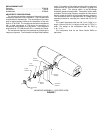
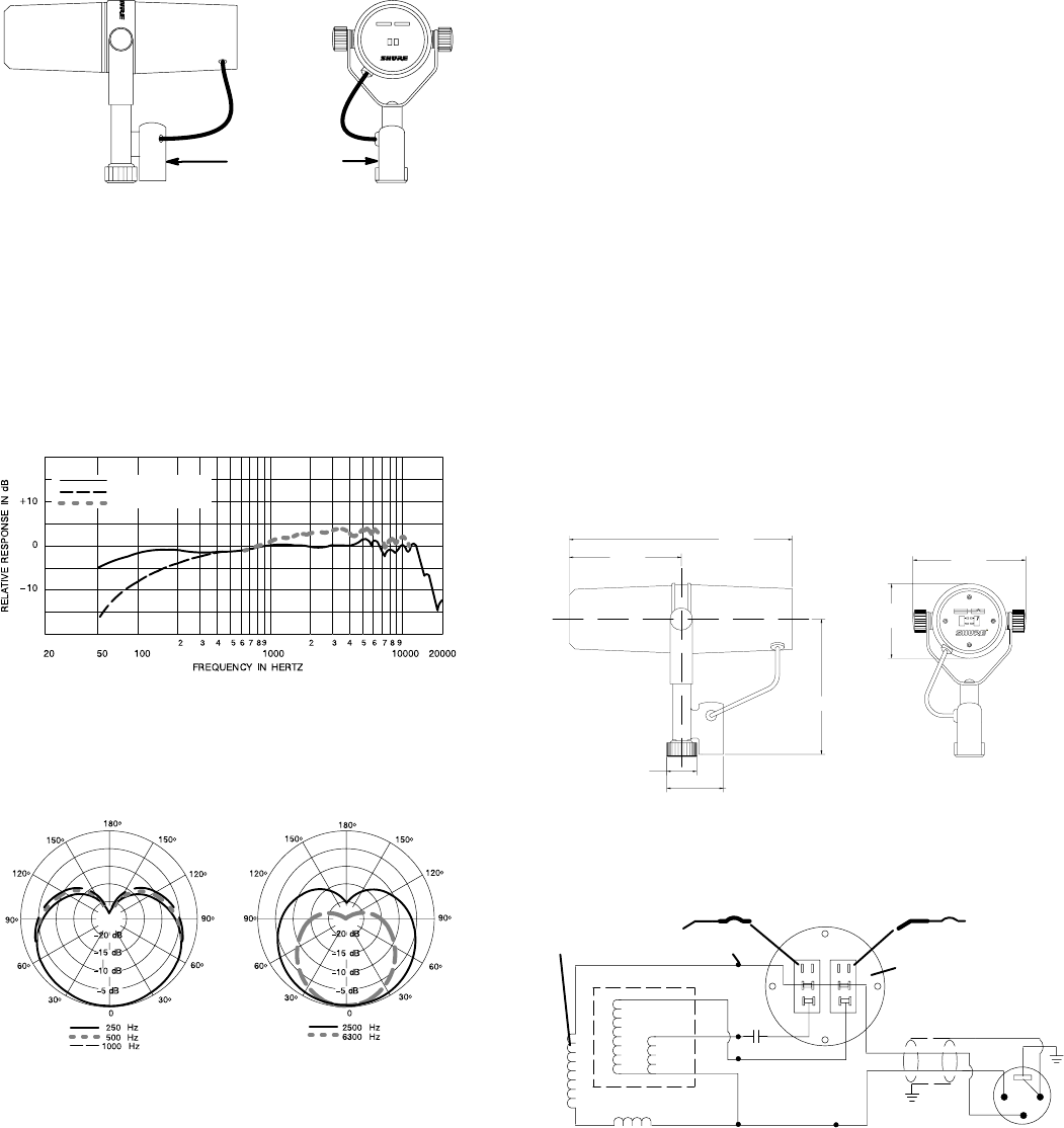
Dimensions
See Figure 5.
95 mm
(3.75 in.)
189.7 mm
(7.469 in.)
25.4 mm
(1.0 in.)
48 mm
(1.890 in.)
117 mm
(4.594 in.)
96 mm
(3.775 in.)
63.5 mm
(2.500 in.)
OVERALL DIMENSIONS
FIGURE 5
Net Weight
765.4 grams (1 lb, 11 oz)
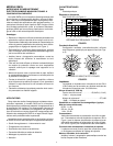
VOICE
COIL
CODED
TERMINAL
BLACK
240 mH
11 mH
HUM BUCKING COIL
.22 µF
x 35 V
YELLOW
GREEN
WHITE
BLACK
CLEAR
CASE
GROUND
GREEN
SHIELD
SWITCH PLATE
(VIEWED FROM
TERMINAL SIDE)
BASS ROLLOFF SWITCH
PRESENCE BOOST SWITCH
1
2
3
INTERNAL CONNECTIONS
FIGURE 6
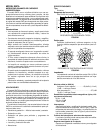
Certification
Eligible to bear CE marking. Conforms to European EMC
Directive 89/336/EEC. Meets applicable tests and perfor-
mance criteria in European Standard EN 55103 (1996)
parts 1 and 2, for residential (E1) and light industrial (E2)
environments.
FURNISHED ACCESSORY
Switch Cover Plate RPM602
. . . . . . . . . . . . . . . . . . . . . . . . . .
OPTIONAL ACCESSORIES
Desk Stand S37A, S39A
. . . . . . . . . . . . . . . . . . . . . . . . . . . . .
Cable and Plug Assembly (7.6m – 25 ft) C25F. . . . . . . . . . . .