


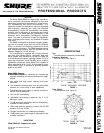
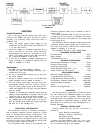
BLOCK DIAGRAM
FIGURE 10
SERVICING
TROUBLESHOOTING
Due to the high packing density and circuit com-
plexity of the SM80, only basic servicing is recom-
mended. The following steps should be taken if
problems arise.
1.
Check the power supply output voltage to the
microphone. For the Shure PS1A, this should be 21.5
± 1.5 Vdc open circuit.
2.
Check the voltage on microphone connector pins 2
and 3 (at back of connector; cable connector
disassembled from shell but connected to micro-
phone). The voltage at pins 2 and 3 with reference to
pin 1 should be between 10 and 48 Vdc.
3.
If more than one SM80 is available, interchange car-
tridge assemblies to determine whether the car-
tridge or amplifier is at fault.
DISASSEMBLY
The SM80 can be disassembled as follows:
1.
Unscrew the grille and cartridge assembly (coun-
terclockwise from top).
2. Lift the 10 dB attenuator actuator ring up and over
the screw threads.
3. Grasp the center contact of the 10 dB attenuator
switch assembly and lift upward to remove it.
4. Turn the slotted head screw near the plug coun-
terclockwide (inward) as far as it will go. Using a
long-nose pliers, grasp one pin of the three-pin con-
nector and withdraw the RFI filter and plug element
from the handle.
5. Remove the low-frequency response switch knob by
placing a small screwdriver or tweezers into the slot
under the ridge of the knob and lifting outward.
6. Remove the small Phillips screw near the plug. Tap
the cartridge end of the handle gently on a firm sur-
face; the printed circuit board and support assembly
will slide out of the cartridge end.
ARCHITECTS’ SPECIFICATION
The microphone shall be a condenser microphone
with a frequency response of 20 to 20,000 Hz. It shall
have an omnidirectional pickup characteristic. The
microphone shall have a rated output impedance of 150
ohms for connection to microphone inputs of 150 ohms
or higher. The open circuit voltage shall be -65 dB (0.56
mV) (0 dB equals 1 volt per microbar).
The microphone shall contain a three-position low-
frequency response switch and a lockable 10 dB at-
tenuator pad.
The overall dimensions shall be 212 mm (8-11/32 in.)
in length by 23.5 mm (15/16 in.) in diameter. The handle
diameter shall be 20.1 mm (25/32 in.). The weight shall
be 230 grams (8 oz).
The microphone shall be capable of being powered by
a phantom (simplex) power supply with an output of 11
to 52 Vdc, or by a mixer, audio console or tape recorder
capable of supplying 11 to 52 Vdc.
The microphone shall be a Shure Model SM80.
FURNISHED ACCESSORIES
Pop
Filter Grille
. . . . . . . . . . . . . . . . . . . . . . . . . . . . . . . . . . . . . . . . . . . . . . . . . . . . . . . . . . .
A81G
Swivel Adapter
. . . . . . . . . . . . . . . . . . . . . . . . . . . . . . . . . . . . . . . . . . . . . . . . . . . . . . . . . . . .
A57D
10 dB
Attenuator
Lock
. . . . . . . . . . . . . . . . . . . . . . . . . . . . . . . . . . . . . . . . . . . .
34A830
OPTIONAL ACCESSORIES
Unidirectional
Microphone Cartridge
. . . . . . . . . . . . . . . . . . . . . . .
R104
Phantom Power
Supply
. . . . . . . . . . . . . . . . . . . . . . . . . . . . . . . . . . . . . . . . . . . . . .
PS1A
Heavy-Duty Windscreen
. . . . . . . . . . . . . . . . . . . . . . . . . . . . . . . . . . . . . . . . .
A81WS
Tripod
Microphone Stand (4.3m - 14 ft)
. . . . . . . . . . . . . . . . . . . . .
S15
Cable (7.6m [25 ft],
XLR connectors)
. . . . . . . . . . . . . . . . . . . . . . . .
C25F
REPLACEMENT PARTS
Grille and Cartridge Assembly
. . . . . . . . . . . . . . . . . . . . . . . . . . . . . . .
R104A
10 dB Attenuator Actuator Ring
. . . . . . . . . . . . . . . . . . . . . . . .
31B1334B
10 dB Attenuator Switch
Assembly
. . . . . . . . . . . . . . . . . . . . .
90B2883
Low-Frequency Response Switch Knob
. . . . . . . . . .
65A1218A
PC Board Assembly and Support
. . . . . . . . . . . . . . . . . . . . . . . .
90B3820
Handle
. . . . . . . . . . . . . . . . . . . . . . . . . . . . . . . . . . . . . . . . . . . . . . . . . . . . . . . . . . . . . . . . . .
31B1392B
RFI
Filter and
Plug Element
. . . . . . . . . . . . . . . . . . . . . . . . . . . . . . . . .
90A3622
GUARANTEE
This Shure product is guaranteed in normal use to be
free from electrical and mechanical defects for a period
of one year from date of purchase. Please retain proof
of purchase date. This guarantee is in lieu of any and all
other guarantees or warranties, express or implied, and
there shall be no recovery for any consequential or in-
cidental damages.
SHIPPING INSTRUCTIONS
Carefully repack the unit, insure it, and return it
prepaid to:
Shure Brothers Incorporated
Attention: Service Department
222 Hartrey Avenue
Evanston, Illinois 60202-3696
If outside the United States, return the unit to your
dealer or Authorized Shure Service Center for repair.
The unit will be returned to you prepaid.
5