


nicht, das Gerät ohne Frequenzzuteilung zu betrei-
ben. Ein Antrag auf Frequenzzuteilung befindet sich
auf den Seiten 15 und 16. Die zuständigen Außen-
stellen sind auf der Karte der Seite 12 ersichtlich
und deren Anschriften auf der Seite 13. Wer die
Anmeldepflicht nicht beachtet, verstößt gegen die
Telekommunikationszulassungsverordnung.
In anderen Ländern muß eventuell eine entspre-
chende Genehmigung beantragt werden. Wenden
Sie sich dazu bitte an Ihre MONACOR-Niederlas-
sung oder an Ihren Fachhändler.
5 Inbetriebnahme
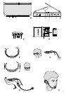
5.1 Montage des Kopfbügelmikrofons
1) Den Kopfbügel je nach eigener Kopfgröße weiten
oder verengen (Abb. 3a).
2) Den Winkel des Ohrbügels ggf. so verändern,
daß ein angenehmer Sitz erreicht wird (Abb. 3b).
3) Das Kopfband auf dem Kopfbügel so verschie-
ben, daß der Bügel fest sitzt (Abb. 3c).
4) Das Mikrofon und den Kabelhalter auf den Bügel
klemmen (Abb. 3d).
5) Den Windschutz auf das Mikrofon stecken.
6) Den Kopfbügel aufsetzen, und das Mikrofon
maximal 15mm vom Mundwinkel entfernt aus-
richten (Abb. 3e).
5.2 Stromversorgung
5.2.1 Empfänger
1) An die Stromversorgungsbuchse SUPPLY 12V
(5) das beiliegende Steckernetzgerät anschließen.
2) Das Netzgerät in eine Steckdose (230V~/50Hz)
stecken.
3) Zum netzunabhängigen Betrieb kann der Emp-
fänger aber auch über eine 12-V-Batterie (z.B.
Autobatterie) versorgt werden. Für den Anschluß
wird ein Kleinspannungsstecker 5,0/2,1mm
(Außen-/Innendurchmesser) benötigt. Dabei un-
bedingt auf die richtige Polarität achten: Den Plus-
pol an den Innenkontakt des Steckers anlegen.
5.2.2 Sender
1) Das Batteriefach öffnen. Eine 9-V-Batterie mit
dem Plus- und Minuspol so herum einsetzen, wie
im Fach aufgedruckt (Abb. 2b).
2) Bei längerem Nichtgebrauch (z.B. länger als
eine Woche) sollte die Batterie herausgenom-
men werden. So bleibt der Sender bei einem
eventuellen Auslaufen der Batterie unbeschädigt.
3) Mit einer frischen Alkaline-Batterie kann das
Mikrofon ca. 7– 8 Stunden betrieben werden.
Leuchtet die Betriebsanzeige (11) nicht bei ein-
geschaltetem Mikrofon, ist die Batterie ver-
braucht und muß ersetzt werden.
●
Werfen Sie verbrauchte Batterien oder defekte
Akkus nicht in den Hausmüll, sondern geben Sie
sie nur in den Sondermüll (z.B. Sammelbehälter
bei Ihrem Einzelhändler).
5.3 Sender anschließen
1) Mit der Klemme (13) den Sender am Gürtel fest-
stecken. Bei Bedarf läßt sich die Klemme um 90°
drehen (rastet ein). Dazu die Schraube der
Klemme etwas lösen und anschließend wieder
festziehen.
2) Das Kopfbügelmikrofon aufsetzen, oder das Kra-
wattenmikrofon an die Kleidung stecken. Das
Mikrofon an die Buchse (15) des Senders an-
schließen. Der Mikrofonstecker läßt sich gegen
Herauslösen sichern, indem die Rändelmutter
des Steckers auf die Buchse geschraubt wird.
3) Mit dem Schalter SENS (16) im Batteriefach die
Eingangsempfindlichkeit einstellen:
Pos.1 beim Anschluß einer E-Gitarre oder einer
anderen Signalquelle mit einem Aus-
gangspegel von max. 600mV
Pos.2 beim Anschluß eines dynamischen Mi-
krofons
Pos.3 für die beiliegenden Mikrofone (Kopf-
bügelmikrofon oder Krawattenmikrofon)
bzw. für ein anderes Elektret- oder Kon-
densatormikrofon (eine Betriebsspan-
nung von 5V liegt an der Kontaktspitze
des Anschlußsteckers an)
5.4 Empfänger anschließen
Zum Anschluß an das nachfolgende Gerät (z.B.
Verstärker, Mischpult) hat der Empfänger zwei Aus-
gänge:
BAL MIC (10) = XLR-Buchse, symmetrisch
zum Anschluß an einen symmetrischen Mikro-
foneingang
AUX (9) = 6,3-mm-Klinkenbuchse, asymmetrisch
zum Anschluß an einen asymmetrischen Mikro-
foneingang oder an einen hochempfindlichen Line-
Eingang (ein passendes Anschlußkabel liegt bei)
Wenn am nachfolgenden Gerät ein symmetrischer
Mikrofoneingang vorhanden ist, sollte die XLR-
Buchse für eine optimale Signalverbindung verwen-
det werden. Den entsprechenden Anschluß zum
nachfolgenden Gerät herstellen. Das nachfolgende
Gerät jedoch erst einschalten bzw. den entspre-
chenden Mischpultregler erst aufziehen, wenn das
Mikrofonsystem komplett eingeschaltet ist.
6 Bedienung
1) Die Antennen (6) senkrecht stellen, ganz heraus-
ziehen und ca. 45° nach außen voneinander
wegschwenken.
2) Den Empfänger mit dem Schalter POWER (4)
einschalten. Die Betriebsanzeige POWER (1)
leuchtet.
3) Die Ansprechschwelle der Störunterdrückung
einstellen. Dazu den Sender noch ausgeschaltet
lassen. Den Regler SQUELCH (7) mit einem klei-
nen Schraubendreher im Uhrzeigersinn in die
Position „MAX. SENSITIVITY“ drehen. Weder die
Empfangsanzeige „A“ noch „B“ (2) darf leuchten.
Leuchtet eine der Empfangsanzeigen, werden
Störungen empfangen. Zur Unterdrückung der
Störungen den Regler SQUELCH gerade so weit
5 Setting the System into Operation
5.1 Mounting the headset microphone
1) Widen or narrow the headset according to your
own head size (fig. 3a).
2) If necessary, modify the angle of the ear piece to
obtain a comfortable fit (fig. 3b).
3) Adjust the headband on the headset to ensure a
tight fit of the headset (fig. 3c).
4) Clamp the microphone and the cable holder to
the headset (fig. 3d).
5) Place the windshield on the microphone.
6) Put on the headset and adjust the microphone in
such a way that it is max. 15mm from the corner
of your mouth (fig. 3e).
5.2 Power supply
5.2.1 Receiver
1) Connect the supplied plug-in power supply unit to
the jack SUPPLY 12 V (5).
2) Connect the power supply unit to a mains socket
(230V~/50 Hz).
3) However, for operation independent of the mains
supply, power supply of the receiver is also pos-
sible via a 12V battery (e.g. car battery). For
connection, a low voltage plug 5.0/2.1 mm (out-
side/inside diameter) is required. Observe the
correct polarity in any case: The positive pole
must be applied to the inner contact of the plug.
5.2.2 Transmitter
1) Open the battery compartment. Insert a 9V bat-
tery with its positive and negative poles as
printed in the compartment (fig. 2b).
2) If the unit is not used for a longer period (e.g. for
more than a week), the battery should be re-
moved to prevent damage to the transmitter in
case of battery leakage.
3) With a new alkaline battery, it is possible to oper-
ate the microphone for approx. 7– 8 hours. If the
power LED (11) does not light up with the micro-
phone switched on, the battery is exhausted and
must be replaced.
●
Exhausted batteries or defective rechargeable
batteries do not belong in the household rubbish:
Always take them to special waste disposal (e.g.
collective container at your retailer).
5.3 Connecting the transmitter
1) Use the clip (13) to fix the transmitter to the belt.
If required, turn the clip by 90° (locks into place).
For this purpose, slightly release the screw of the
clip and then tighten it again.
2) Put on the headset microphone or attach the tie-
clip microphone to your clothes. Connect the
microphone to the jack (15) of the transmitter. To
prevent the plug of the microphone from releasing
itself, screw the knurled nut of the plug to the jack.
3) Adjust the input sensitivity by means of the switch
SENS (16) in the battery compartment:
pos. 1 for connecting an electric guitar or an-
other signal source with an output level
of max. 600mV
pos. 2 for connecting a dynamic microphone
pos. 3 for the supplied microphones (headset
microphone or tie-clip microphone) or
another electret or capacitor microphone
(a 5V operating voltage is applied to the
contact tip of the connector plug)
5.4 Connecting the receiver
The receiver is equipped with two outputs to connect
the subsequent unit (e.g. amplifier, mixer):
BAL MIC (10) = XLR jack, balanced
to connect a balanced microphone input
AUX (9) = 6.3mm jack, unbalanced
to connect an unbalanced microphone input or a
highly sensitive line input (a matching connecting
cable is supplied with the unit)
If the subsequent unit is provided with a balanced
microphone input, the XLR jack should be used for
an optimum signal connection. Make the correspond-
ing connection to the subsequent unit. Do not switch
on the subsequent unit or do not advance the corre-
sponding control on the mixer until the microphone
system has been completely switched on.
6 Operation
1) Place the antennas (6) in a vertical position,
extract them to their full length and turn them
away from each other, at a degree of approx. 45°
outwards.
2) Switch on the receiver with the POWER switch
(4). The POWER LED (1) lights up.
3) Adjust the muting threshold. For this purpose,
leave the transmitter switched off for the time
being. Use a small screw driver to turn the
SQUELCH control (7) clockwise to the position
“MAX. SENSITIVITY”. Neither reception LED “A”
nor “B” (2) must light up.
If one of these reception LEDs lights up, inter-
ferences are received. To suppress these inter-
ferences, turn back the SQUELCH control
counterclockwise until the reception LED is just
extinguished. Do not turn the control counter-
clockwise any further, otherwise the transmission
signal may also be suppressed.
4) Switch on the transmitter with the POWER switch
(12). The power LED (11) lights up. If it remains
dark, the battery is exhausted and must be re-
placed.
Slide the POWER switch fully to the left to the
position ON. In mid-position, the transmitter is
mute, i.e. the transmitter is switched on, how-
ever, no sound is transmitted.
5) After switching on the receiver and the transmit-
ter, one of the reception LEDs (2) on the receiver
must light up. If it remains dark, the reception is
too poor:
a Is the transmitter battery exhausted?
5
GB
D
A
CH