


2
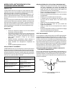
STAGE MONITOR & P.A. LOUDSPEAKER PLACEMENT
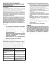
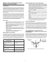
For maximum rejection of unwanted sound, place the stage moni-
tor(s) or P.A. system loudspeaker at a 60° angle from the rear of
the BETA 58A, not directly behind it. Always check out the stage
setup before a performance to ensure that microphone and moni-
tor placement is optimum.
SPECIFICATIONS
Type
Dynamic (moving coil)
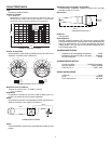
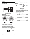
Frequency Response
50 to 16,000 Hz
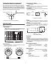
NOTE: The curve below shows on-axis response at a distance of 2
feet from a uniform sound source. Your response may vary, depend-
ing on microphone position.
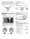
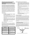
Polar Pattern
Supercardioid, rotationally symmetrical about microphone axis,
uniform with frequency
Output Level (at 1,000 Hz)
Open Circuit Voltage: -51.5 dBV/Pa* (2.6 mV)
*1 Pa = 94 dB SPL
Impedance
Rated impedance is 150 Ω (290 Ω actual) for connection to micro-
phone inputs rated low Z
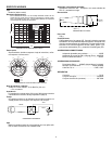
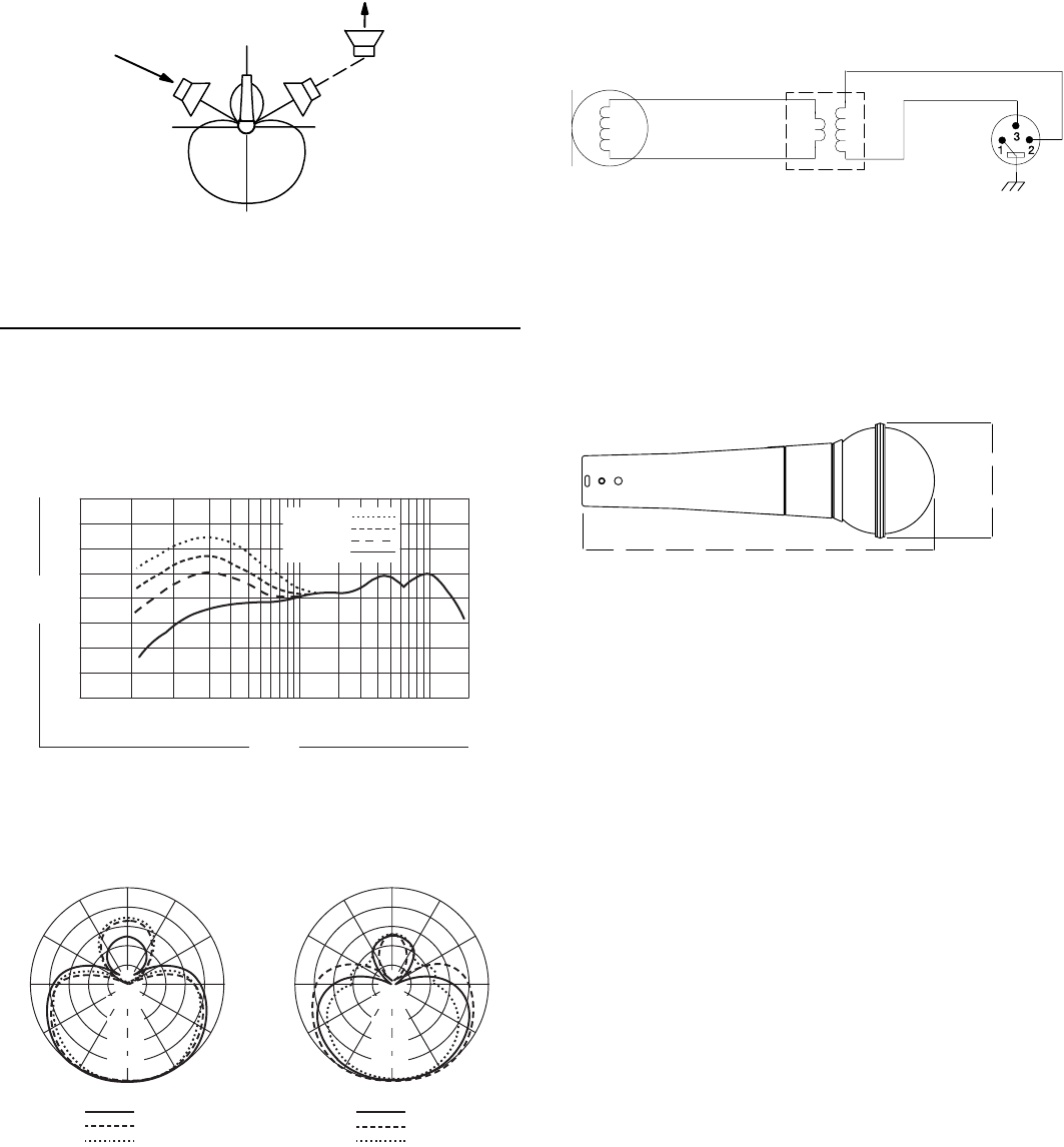
Phasing
Positive pressure on diaphragm produces positive voltage on
pin 2 with respect to pin 3
Case
Silver blue enamel-painted die cast metal with hardened, matte-
finished, spherical steel mesh grille
Adjustable, Stand Adapter
Slip-in microphone mounting, unbreakable, adjustable through
180° with standard 5/8"-27 thread, black finish
Dimensions
Net Weight
278 grams (9.92 oz)
Certification
Eligible to bear CE Marking. Conforms to European EMC Direc-
tive 89/336/EEC. Meets applicable tests and performance crite-
ria in European Standard EN55103 (1996) parts 1 and 2, for
residential (E1) and light industrial (E2) environments.
FURNISHED ACCESSORIES
Adjustable Stand Adapter ...................................... A25D
5/8" to 3/8" (Euro) Thread Adapter ...................95A2050
Storage Bag .......................................................... 26A21
OPTIONAL ACCESSORIES
Windscreen...............A58WS Series (8 colors available)
Isolation Mount.........................................A55M, A55HM
7.6 m (25 ft.) Cable ......................................C25E, C25F
REPLACEMENT PARTS
Cartridge.................................................................R176
Grille Assembly..................................................RK265G
Plug (Connector) Assembly .............................. 90F1984
180°
120°120°
90°
0°
P.A. SYSTEM
LOUDSPEAKER
MONITOR
LOUDSPEAKER(S)
RECOMMENDED LOUDSPEAKER LOCATIONS
20 200001000 1000050 100
9876543298765432
+10
0
–10
Hz
dB
-20
+20
3 mm (1/8 in)
25 mm (1 in)
51 mm (2 in)
606 mm (2 ft)
TYPICAL FREQUENCY RESPONSE
150°
120°
150°
120°
180°
30°
60°
90°
30°
60°
0
90°
–10 dB
–20 dB
–15 dB
–5 dB
150°
120°
150°
120°
180°
30°
60°
90°
30°
60°
0
90°
–10 dB
–20 dB
–15 dB
–5 dB
500 Hz
1000 Hz
250 Hz
6300 Hz
10000 Hz
2500 Hz
TYPICAL POLAR PATTERNS
GREEN
YELLOW
RED
BLUE
INTERNAL WIRING
160 mm
(6.5 in.)
50 mm
(2 in.)
OVERALL DIMENSIONS