


SPECIFICATIONS WL50
{
WL50–LO
{
MC50
}
WL51
{
MC51
}
Type Condenser (electret bias) Condenser (electret bias) Condenser (electret bias) Condenser (electret bias) Condenser (electret bias)
Polar Pattern Omnidirectional Omnidirectional Omnidirectional Cardioid Cardioid
Output Impedance N/A N/A 136 W actual (rated at 150 W) N/A 136 W actual (rated at 150 W)
Recommended Min. Input
Impedance
20 kW 20 kW N/A 20 kW N/A
Output Level –45.0 dBV/Pa
(1 Pa=94 dB SPL)
–54.0 dBV/Pa
(1 Pa=94 dB SPL)
–41.0 dBV/Pa
(1 Pa=94 dB SPL)
–50.0 dBV/Pa
(1 Pa=94 dB SPL)
–46.0 dBV/Pa
(1 Pa=94 dB SPL)
Maximum SPL 133 dB at 1% THD/
20k W load
142 dB at 1% THD/
20k W load
138 dB at 1% THD/
1 k ohm load
138 dB at 1% THD/
20k W load
143 dB at 1% THD/
1 k ohm load
Frequency Response 20 to 20,000 Hz (see Figure 5)
Dynamic Range 103.0 dB 103.0 dB 108.0 dB 103.0 dB 108.0 dB
Output Noise
(equivalent SPL, A-weighted)
30 dB typical; 33 dB maximum 39 dB typical; 42 dB maximum 30 dB typical; 33 dB maximum 35 dB typical; 38 dB maximum 35 dB typical; 38 dB maximum
Signal-to-Noise
Ratio
64 dB at 94 dB SPL 55 dB at 94 dB SPL 64 dB at 94 dB SPL 59 dB at 94 dB SPL 59 dB at 94 dB SPL
Power Requirements +5 Vdc on pin 2, return on pin 1
(ground).
+5 Vdc on pin 2, return on pin 1
(ground).
11 to 52 Vdc (positive on pins 2
and 3, return on pin 1).
+5 Vdc on pin 2, return on pin 1
(ground).
11 to 52 Vdc (positive on pins 2
and 3, return on pin 1).
Current Drain 60–130 mA 60–130 mA 4.6 mA 60–130 mA 4.6 mA
Polarity—Positive pressure on
the diaphragm produces a
positive voltage at:
Pin 3 relative to pin 1 at the output connector of the microphone. pin 2 relative to pin 3 of the output
connector of preamplifier.
pin 3 relative to pin 1 at the
output connector of the
microphone.
pin 2 relative to pin 3 of the output
connector of preamplifier.
Overvoltage Protection N/A N/A ±75.0 Vdc maximum from pins
2 and 3 to pin 1.
N/A ±75.0 Vdc maximum from pins
2 and 3 to pin 1.
Cap and Overmold Material Polypropylene
Environmental Conditions Operating Temperatures: –18
_
to 57
_
C (0
_
to 135
_
F) Storage Temperatures: –29
_
to 74
_
C (–20
_
to 165
_
F) Humidity: 0 to 95%
Packaged Weight 188 g (6.63 oz.) 188 g (6.63 oz.) 305 g (10.76 oz.) 188 g (6.63 oz.) 305 g (10.76 oz.)
Cable and
Connector
1.5 m (5 ft.), small-diameter,
shielded, with miniature female
4-pin connector (TA4F type).
WL50X: 3 m (10 ft.)
small-diameter, shielded, with
stripped and tinned leads.
1.5 m (5 ft.), small-diameter,
shielded, with miniature female
4-pin connector (TA4F type).
WL50X–LO: 3 m (10 ft.)
small-diameter, shielded, with
stripped and tinned leads.
1.5 m (5 ft.), small-diameter,
shielded, with miniature female
4-pin connector (TA4F type).
1.5 m (5 ft.), small-diameter,
shielded, with miniature female
4-pin connector (TA4F type).
WL50X: 3 m (10 ft.)
small-diameter, shielded, with
stripped and tinned leads.
1.5 m (5 ft.), small-diameter,
shielded, with miniature female
4-pin connector (TA4F type).
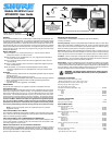
Microphone and Preamp
Dimensions
See Figures 2 and 3
Net Weight WL50: 21 g (0.7 oz.) with cable
and connector.
WL50X: 28 g (1.0 oz.) with 3 m
(10 ft.) stripped and tinned
cable.
WL50–LO: 21 g (0.7 oz.) with
cable and connector.
WL50X–LO: 28 g (1.0 oz.) with
3 m (10 ft.) stripped and tinned
cable.
121 g (4.3 oz.) with cable,
connector, and preamplifier.
WL51 21 g (0.7 oz.) with cable
and connector. WL51X: 28 g
(1.0 oz.) with 3 m (10 ft.)
stripped and tinned cable.
121 g (4.3 oz.) with cable,
connector, and preamplifier.
Certification: Eligible to bear CE marking. Conforms to European EMC directive
89/336/EEC. Meets applicable test and performance criteria in European EMC standard EN
55103 (1996) parts 1 and 2, for residential (E1) and light industrial (E2) environments.
{
Measured with test circuit (see Figure 1).
}
Measured with RPM626 Preamplifier.
99 mm
(3.89 in.)
20 mm DIA.
(.79 in.)
14 mm
(.55 in.)
19 mm DIA.
(.75 in.)
1.52 m (5 ft.) for WL50/MC50 and WL51/MC51 Series
5.8 mm (.23 in.)
3.04 m (10 ft.) for WL50X/WL51X Series
5.8 mm (.23 in.)
PREAMPLIFIER DIMENSIONS
MICROPHONE AND CABLE DIMENSIONS
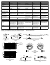
RELATIVE RESPONSE IN dB
On Axis
180
o
Off Axis
Omnidirectional
RELATIVE RESPONSE IN dB
High Boost
Equalization Cap
Mild Boost
Equalization Cap
TYPICAL FREQUENCY RESPONSE
Cardioid
2500 Hz
6400 Hz
10000 Hz
150
o
120
o
150
o
120
o
180
o
30
o
60
o
90
o
30
o
60
o
0
90
o
–5 dB
–10 dB
–15 dB
–20 dB
250 Hz
500 Hz
1000 Hz
150
o
120
o
150
o
120
o
180
o
30
o
60
o
90
o
30
o
60
o
0
–5 dB
–10 dB
–15 dB
90
o
–20 dB
TYPICAL POLAR PATTERN
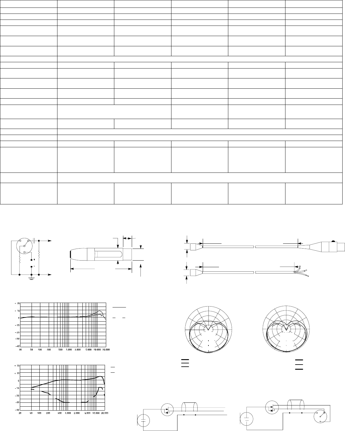
CARDIOID
CONDENSER CAR-
TRIDGE
IMPEDANCE
CONVERTER
RED
BLK
SHIELD
GROUND
AUDIO OUT
+5 Vdc
S
G
D
+
WL50X SERIES MICROPHONE WIRING DIAGRAM
(UNTERMINATED)
RED
IMPEDANCE
CONVERTER
CONDENSER
CARTRIDGE
BLK
SHIELD
3
4
2
1
S
G
D
Audio Out
+5 Vdc
WL50/MC50 and WL51/MC51 SERIES MICROPHONE
WIRING DIAGRAM WITH TA4F CONNECTOR
100 k
1.0 uf
5 Vdc
20 k
1
2
3
4
STANDARD TEST CIRCUIT
FIGURE 1
FIGURE 2
FIGURE 3
FIGURE 4
FIGURE 5
FIGURE 6 FIGURE 7