14
ENABLING THE EXTERNAL MUTE FEATURE
The factory default is that this feature is disabled. There is therefore no need to fit a shorting wire between the two n.c. (normally
closed) contacts if you do not want to use this feature.
To enable this feature the internal switch which shorts the two n.c. contacts must be opened. Before doing this ensure that the
mains is switched off and the mains lead is removed from the mixer.
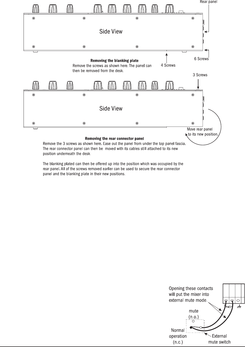
Remove the rear panel as described in the instuctions above (moving the rear
connector panel). This will allow access to the internal switch.
The switch is located on a small pcb which is behind the red external mute connector,
The switch must be depressed to enable the exturnal mute reature. The switch is a
push-on, push-off type.
Replace the rear connectior panel and secure with the screws removed earlier.
A user-provided external-mute switch must be wired between the two rear panel
contacts as shown.
MOVING THE REAR CONNECTOR PANEL
It is possible to move the rear connector panel from its factory default position to its alternative location underneath the console. This
alternative position can make it easier to rack or furniture-mount the console. To move the rear connector panel proceed as shown
in the following diagram.
REPOSITIONING THE RACK EARS
The rack ears are shipped fitted to the sides of the console, but they are upside-down with the ears tucked underneath the
console. To reposition them to allow furniture/rack fitting proceed as follows:
Note that the ears are not identical, there is left hand and a right hand ear. It is best to reposition one side completely before
starting on the other one. Undo the 8 screws which hold the ear onto the side of the console. Rotate the ear so that it is level with
the top of the console and is facing outwards. Replace the 8 screws. Repeat this operation for the other ear.


