


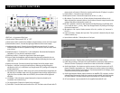
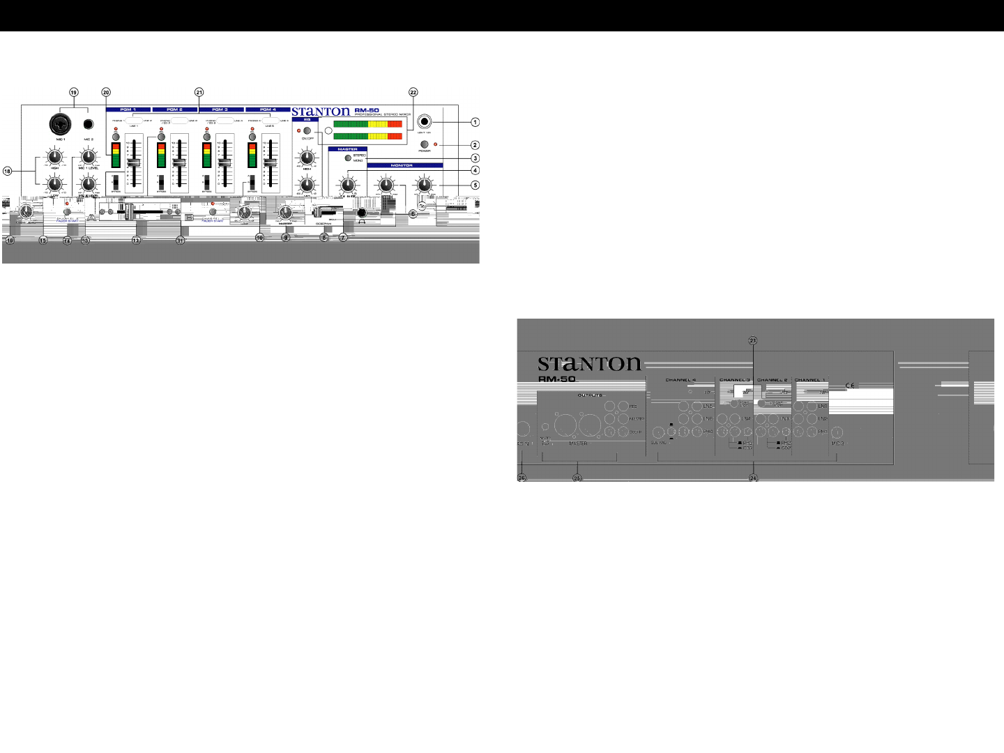
D E S C R I P T ION OF F U N C TI O N S
1. BNC jack: 12V gooseneck light input
2. Power switch: Selects power "ON" or "OFF"
3. Mono/stereo switch: switches the of Master output between a stereo and mono signal
4. Master balance control: Controls left/right signal balance of the master output.
5. Headphone level control: Controls the overall headphone output level. It is recom-
mended headphones with an impedance rating of 200 ohms or less be used for maxi-
mum volume.
6. Headphone output: Connection for 1/4 inch headphone. Recommended headphone
impedance is 32-200 ohms for maximum volume.
7. Booth level control: Controls the signal level of the booth output.
8. Cue pan: Fades the headphone output between the channel(s) selected by the cue
assign switches (17) and the master one output, effectively allowing the user to pre-
view a mix.
9. Master level control: Controls the overall signal output level of the master output.
10. Equalizer: Individual controls for low frequency, midrange, and high frequency
equalization with (+10/-10 dB) Note: Any changes made to EQ settings will change the
overall output level.
11. Crossfader source selectors: When set to A, the select channel will be assigned to the
left side of the crossfader. when set to B, the selected channel will be assigned to the
right side of the crossfader. When set to BYPASS, the crossfader will be bypassed
altoghter.
12 . Crossfader: Fades the master output between the channels selected by the
Crossfader source selectors (13).
13. Cue assign switch: Selects the channel to be monitored.
14. Fader Start: Turns the fader start function ON or OFF. The fader start will work with CD
22. Output Level meter: Displays the overall signal level of the master output.
23. Fader Start connector: Connects to the sound module’s remote start output (such as
Stanton’s S-Series CD players) to control the cue-start via the mixer’s crossfader.
24. Audio signal inputs: Line inputs are used to connect to line level sources such as CD
players, samplers, tape players, etc. Phono inputs are used to connect to turntables.
Mic inputs connect directly to microphones. To prevent potential circuit damage, never
connect line level source to phono inputs.
25. Audio signal outputs: Master output connects to an amplifier, EQ, crossover, or other
outboard signal processing. Record out connects to tape recorder, mini disk recorder,
etc. Booth output is a second master output used mostly for in-booth monitoring.
26. AC cord connector: Input connection for the supplied removable AC cord.
players (such as Stanton’s S-Series) to start the audio from the CD player’s cue point.
15. Channel fader: Controls the input channel level.
16. Microphone volume: Controls the output levels of mics 1, 2, and 3.
17. Mic selector: Turns the mic on or off and activates the automatic talkover circuit.
When activated, the automatic talkover circuit reduces the music output based on the
setting of the talkover attenuation control (19).
18. Mic EQ: Individual controls for low frequency and high frequency equalization with
(+10/-10 dB) for mics 1, 2, and 3. Note: Any changes made to EQ settings will change
the overall output level.
19. Microphone 1 and 2 inputs: Combo connector is for mic 1, and the 1/4” connector is
for mic 2.
20. Input Level meter: Displays the input level. The input level is determined by the input
channel controls (24).
21. Input selector switches: Selects phono or line input.