Rack Mount In stal la tion
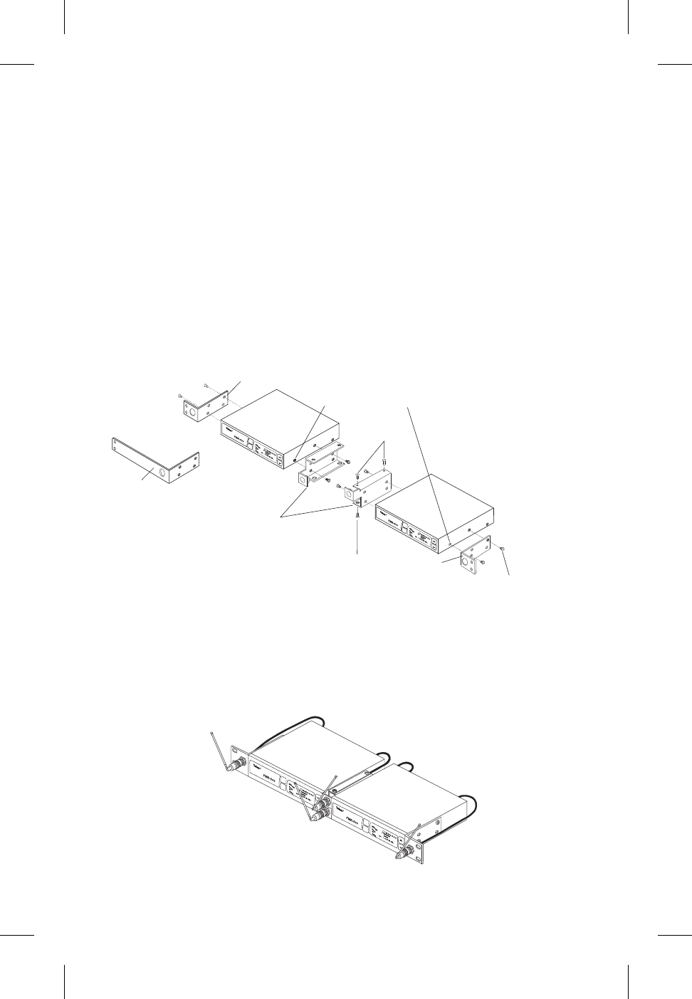
The FMR-500 is sup plied with rack mounts for sin --
gle and dou ble mount ing in a stan dard EIA 19"/
483mm equip ment rack (see Fig ure 3). For rack
mount ing a sin gle unit, a long (#3) and short (#1)
"ear" are used. For dual side-by-side mount ing, use
the short (#1) "ears" and the mid brack ets (#2) from
two FMR-500's as shown.
To as sem ble the rack mount adapt ers to the
FMR-500 pro ceed as fol lows:
1. Re move the front Phillips head screws from
each side of each unit.
2. Align the cor rect rack ear or bracket with the
holes on the side of the unit. In stall the pre vi --
ously re moved screws. In sert an ad di tional
screw (#2, pro vided in the parts pack) into the
re main ing hole. Re peat this step for the op po site
side of the unit. Be sure to tighten all screws se --
curely.
Front Mount ing An ten nas
1. Re move hole plugs from brack ets.
2. At tach the an tenna con nec tors to the brack ets.
Four dou ble mount ing of two FMR-500's pro ceed
as fol lows:
1. Align the mid brack ets (#2) with the holes on
the ad ja cent sides of each unit.
2. In stall the pre vi ously re moved screws. In sert an
ad di tional screw (#4, pro vided in the parts pack)
into the re main ing holes. Tighten all screws se --
curely.
3. Place the two as sem blies side-by-side with the
mid brack ets to gether. (The left bracket should
fit above the right so that the coun ter sinks are
vis i ble). In stall 4 flat head screws (#5, pro vided
in the parts pack) and tighten them se curely.
3. At tach the sup plied ex ten sion ca bles from the
rack con nec tors to the an tenna con nec tions on
the back of the re ceiver. See Fig ure 4.
-4-
s
e
t
p
o
we
r
R
R
C
L
EA
R
S
C
A
N
s
e
t
p
ow
e
r
R
R
C
L
E
A
R
S
CA
N
(TYPICAL BOTH SIDES)
(TYPICAL ALL SIDES)
1
1
4
REMOVE SCREWS
(TYPICAL 4 SIDES)
2
5
5
3
s
e
t
p
o
w
er
RR
CL
EAR
S
C
A
N
s
e
t
p
ower
RR
C
L
E
A
R
S
C
A
N
Fig ure 3
Rack Mount Installation
Fig ure 4
Front Mount ing Antennas


