


Power Source AC mains, 50/60 Hz
Power Consumption 40W
Audio Input Max. 8 channels, modular construction (modules optional)
Audio Output Preamplifier output 1 2: 0 dBV, 600Ω, balanced, removable terminal block (3 pins)
Module Slot Analog input (slot 1 – 8): –10dB*, unbalanced
Digital input (slot 1– 4): 24 bit/48kHz
MIX output (slot 1 – 8): -14dB*, 330 Ω (CH 1 prefader output), unbalanced
Digital output (slot 5 – 7): 24 bit/48kHz
Power supply (slot 1 – 8): 24V, -24V, :6V DC
Digital Audio Dignal Reference Level –20dBFS
Frequency Response 20 – 20,000 Hz +1, –3 dB
Total Harmonic Distortion 0.008% (at 22 kHz LPF, 1 kHz, +10 dBV output)
S/N Ratio At Input short, 20 – 20,000 Hz, ALL FLAT or OFF setting
Output volume min.: 90 dB
Output volume max.: 61 dB (input 1 vol.: 0 dB, other inputs: OFF)
Crosstalk Over 64 dB (at 20 kHz)
Tone Control Bass: +/–12 dB (at 100 Hz), Treble: +/–12 dB (at 10 kHz)
Parametric Equalizer 10 bands, Freq: 20 – 20,000Hz, 31 steps, Various range: +/–12 dB, Q: 0.3 – 5
Speaker Equalizer 15 (presets for TOA speakers)
High-pass Filter –12 dB/oct, Variable frequency range: 20 – 400 Hz, 14 steps
Low-pass Filter –12 dB/oct, Variable frequency range: 4,000 – 20,000 Hz, 8 steps
Compressor Depth: 1 – 5
Delay 0 – 40 ms (1 ms steps), maximum 40 ms (CH1 + CH2) (Mixer mode only)
Scene/Event Memory 32
Operation Mode Matrix mode/Mixer mode (selector switch)
Auxiliary Function Key lock function
Control Input/Output RS-232C*
2
, D-sub connector (9P, female)
Control input: 4 inputs, no-voltage make contact input, open voltage: 3.3 V DC, short-circuit current: under 1 mA, removable terminal block (14 pins)
Control output: 4 outputs, open collector output, withstand voltage: 27 V DC, control current: 50 mA, removable terminal block (14 pins)
Remote volume: 2 channels, connect a 10kΩ/linear taper variable resister or input the DC voltage of 0 to +10V, removable terminal block (14 pins)
Operating Temperature –10°C to 40°C
Operating Humidity 35% to 80% RH (no condensation)
Finish Panel: Aluminum, hair-line, black, Case: Surface-treated steel plate, black paint
Dimensions (W × H × D) 420 × 107.6 × 353 mm
Weight 6 kg (without modules)
Accessory Power cord (2m) × 1, Rack Mounting bracket × 2, Bracket mounting screw × 4, Blank panel × 7, Blank panel mounting screw × 14,
Removable terminal plug (3 pins) × 2, Removable terminal plug (14 pins) × 1, CD-ROM × 1, Start guide × 1
* 0dB = 1V
*
2
Allowing it to be controlled by a control system such as AMX and Crestron through RS-232C port.
Notes: AMX is a tradmark of AMX Corporation. Crestron is a tradmark of Crestron Electronics. Inc.
M-9000
Digital Matrix Mixer
SPECIFICATIONS
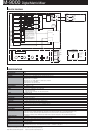
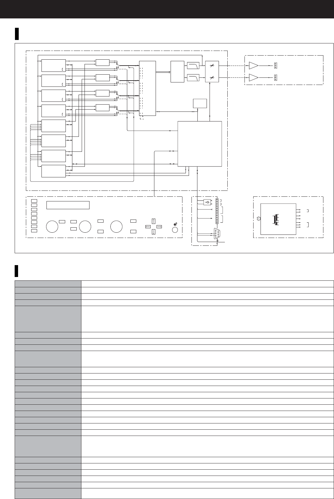
BLOCK DIAGRAM
INPUT SELECT
INPUT VOLUME
Vacuum Fluorescent Display
1
2
3
4
5
6
7
8
OUTPUT SEL
OUTPUT VOLUME
PARAMETER
ESC/BACK
UTILITY
ENTER
MEMORY
ON/OFFON/OFF
POWER
DIN
#1
#2
ADC
#1
#8
ADC
#2
#7
DIN
#3
#4
ADC
#3
#6
ADC
#4
#5
DIN
#5
#6
DIN
#7
#8
SLOT#1
MIX OUT
DAC
1
DSP
R–>V
CONVERT
REMT-VOL1
REMT-VOL2
RS232
MODE SW
MATRIX/MIXER
CONTROL
INPUT
CONTROL
OUTPUT
1
2
3
4
5
6
7
8
9
10
11
12
13
14
H
E
H
E
CI1
CI2
CI3
CI4
E
CO1
CO2
CO3
CO4
E
DI1
DIS1
ANALOG
DIGITAL
DI2
DIS2
DI3
DIS3
DI4
DIS4
EEPROM
I2C
CPU
DI1
DI2
DI3
DI4
DI1
DI2
DI3
DI4
DI1
DI2
DI3
DI4
TXDM8
RXDM8
I2C
DOUT
1
2
3
4
5
6
7
8
2
SLOT#2
MIX OUT
SLOT#3
MIX OUT
SLOT#4
MIX OUT
SLOT#5
MIX OUT
Dout 1
Dout 2
Dout 3
Dout 4
Dout 1
Dout 2
Dout 3
Dout 4
Dout 1
Dout 2
Dout 3
Dout 4
SLOT#6
MIX OUT
AIN
AIN
AIN
AIN
AIN
AIN
AIN
AIN
SLOT#7
MIX OUT
SLOT#8
MIX OUT
TXD
RXD
LPF
LPF
VOLUME
CONTROL
TXD
I2C
RXD
CONTROL I/O
INPUT SELECT SIGNALS
KEY&DISPLAY CONTROL
RXD
TXD
MODE
232RXD
232TXD
POWER SUPPLY
AC IN
MAIN_TRANS
+24 V
–24 V
ANALOG
+6 V
DSP/AD/DA
+3.3 VBU
CPU
–30 V
AC5 V
VFD
AC5 V
PRE
AMP
OUT 1
H
C
E
H: Hot
C: Cold
E: Earth
PRE
AMP
OUT 2
H
C
E
NE5532
NE5532
M-9000
VOLUME
ANALOG
DIGITAL
ANALOG
DIGITAL
ANALOG
DIGITAL
I2C
I2C
I2C
I2C
I2C
I2C
I2C
I2C
I2C
1
8
1
2
1
2
2
7
3
6
4
5
at ANALOG INPUT
at DIGITAL INPUT
INTERNAL ADC / MODULE I2S
SIGNAL SELECTORS
Remarks
Each pair of Inputs 1 and 8, 2 and 7, 3
and 6, and 4 and 5 is the analog inputs
of ADC (Analog-Digital Converter).
So, when a digital input module such as
the D-001T is inserted into Slot 1, for
example, the digital input selector DIS1
is switched over to the DIGITAL position,
thereby disabling the use of analog
Inputs 1 and 8.
Consequently, Slot 8's analog input
(AIN) cannot be used.
Likewise, when Slot 2 is occupied by the
D-001T, Slot 7's analog input cannot be
used; and when Slot 3 is occupied, Slot
6's analog input cannot be used.