


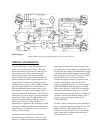
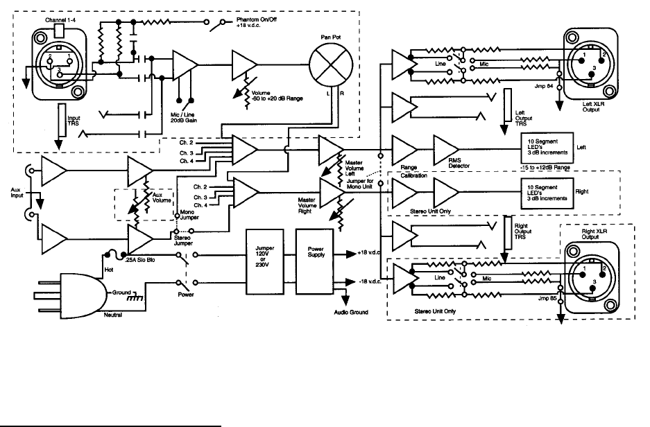
Block Diagram:
Right channel sections and pan pots apply only to the Mix 5 Stereo.
THEORY OF OPERATION
All of the XLR and 1/4” input and output jacks are
active, electronically balanced circuits. The input
section and all critical gain sections of the Mix 5 use
the same IC for gain as top professional mixing
boards. This IC, along with careful component
selection and PC board layout, enables the Mix 5 to
achieve professional quality signal reproduction. All
the gain controls on the Mix 5 (Channel Gain, Aux
and Master) have a range of -60 to +20dBm. With the
input and output switches in the Line position and
both the channel and master volume controls at the
same settings, unity gain is approximately at the 9
O’clock knob position, 10dB gain at 12 O’clock, and
15dB gain at 3 O’clock. At the 5 O’clock position the
unit provides 35dB of gain. The Mic position of the
input switch provides another 20dB for a total of
55dB of gain. This feature allows the Mix 5 to
adequately mix equipment with a wide range of audio
level outputs. 60dB of attenuation in the Off position
allows the Mix 5 to adequately “turn off” line level
signals at the Mix 5 inputs.
The output section of the Mix 5 was designed to
accommodate any configuration – line or mic level;
XLR or ¼”; balanced or unbalanced. Each channel’s
output jacks are individually buffered so that using
any combination of the outputs at any impedance will
not affect the other outputs. With the Mic/Line switch
in the Mic position, the XLR output is reduced 20dB
(this switch does not affect the 1/4” jacks). The Mix 5
uses an H-Pad resister network at the XLR to
maintain the signal to noise ratio, regardless of the
position of the Mic/Line switch. For the XLR
outputs, if ground lifting of pin 1 is desired, jumpers
JMP 84 and JMP 85 inside the unit can be clipped.
Then, in Line mode pin 1 of the XLR is completely
lifted and in Mic mode the XLR’s pin 1 is ground
isolated and referenced to pins 2 and 3. If unbalanced
operation is desired from the XLR outputs, pin 2 is
hot, pin 1 is ground, and pin 3 should be left
UNCONNECTED.
The Mix 5 utilizes a dual primary power transformer
that is configured with internal jumpers for 120 VAC
60Hz or 230 VAC 50Hz operation. There is an
internal fuse on the hot side of the AC cord, and the
power switch makes and breaks both the hot and
neutral legs of the AC cord.