


1
i
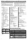
NOTE
• We do not recommend attempting to assemble the
Clavinova alone. The job can be easily accomplished,
however, with only two people.
• Use only the screws provided or replacements of
exactly the specified size. Using screws of the wrong
size can result in damage to the instrument.
Z
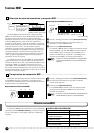
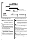
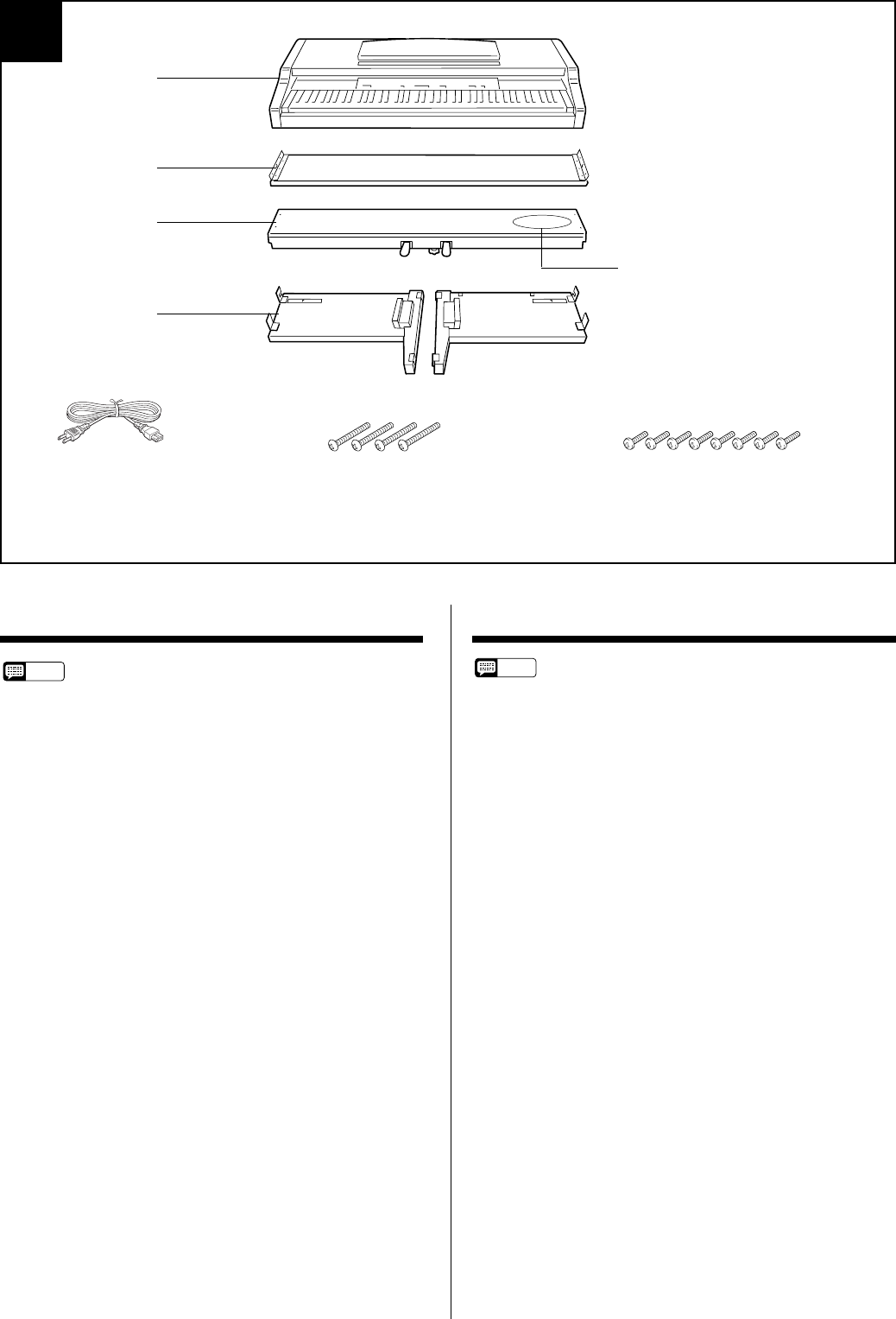
Open the box and remove all the parts.
On opening the box you should find the parts shown in the
illustration above. Check to make sure that all the required parts
are provided.
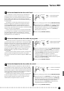
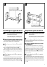
X
Attach the side panels (D) to the pedal box
(C).
Before installing the pedal box, untie and straighten out the
bundled cord attached to the bottom of the pedal box. Don’t dis-
card the vinyl tie, you’ll need it later in step B.
Place the pedal box on top of the wooden blocks attached to
the side panels (D), and attach using the four 6 x 35 millimeter
round-head screws 1 — two screws on each side. Make sure the
pedals extend in the same direction as the feet.
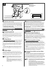
C
Attach the center panel (B) to the side pan-
els (D).
The center panel (B) is installed between the side panels (D)
with the brackets on each end toward the rear of the stand assem-
bly. Place the square holes in the center-panel brackets over the
lugs extending from the side panels, then slide down. Each side
of the center panel is attached using two 6 x 16 flat-head screws
2.
HINWEIS
• Wir raten davon ab, das Clavinova alleine zusammenzu-
bauen und aufzustellen. Zwei Personen können diese
Arbeit jedoch problemlos ausführen.
• Verwenden Sie ausschließlich die mitgelieferten Schrau-
ben oder Ersatzschrauben identischer Größe. Die Ver-
wendung von Schrauben mit abweichenden Maßen kann
eine Beschädigung des Instruments zur Folge haben.
Z
Öffnen Sie den Karton und nehmen Sie alle
Teile heraus.
Im Karton sollten die oben abgebildeten Teile enthalten sein.
Prüfen Sie zunächst bitte, ob alle Teile vollständig vorhanden sind.
X
Schrauben Sie den Pedalkasten (C) an den
Seitenwänden (D) fest.
Bevor Sie den Pedalkasten montieren, nehmen Sie zunächst das
gebündelte Kabel aus dem Pedalkasten, entfernen den Kabelbinder
und ziehen das Kabel dann gerade aus. Werfen Sie den Kabelbinder
nicht wg, er wird in Schritt B wieder gebraucht.
Setzen Sie den Pedalkasten auf die Holzklötze an den Seiten-
wänden (D), und schrauben Sie ihn dann mit den vier 6 x 35 mm
Halbrundschrauben 1 fest (jeweils zwei Schrauben links und
rechts). Achten Sie dabei darauf, daß die Pedale in dieselbe Rich-
tung weisen wie die vorspringenden Teile der Füße.
C
Schrauben Sie die Rückwand (B) an die bei-
den Seitenwände (D).
Die Rückwand (B) wird mit den Winkelblechen an beiden Enden
nach hinten weisend an den Seitenwänden (D) befestigt. Lassen Sie
dabei die Führungsnasen an den Seitenwänden in die
Schlitzbohrungen in den beiden Winkelblechen greifen, und drücken
Sie die Rückwand dann nach unten. Sichern Sie die Rückwand dann
mit jeweils zwei kurzen schwarzen Schrauben 2 an den Seiten-
wänden.
Zusammenbau und AufstellungKeyboard Stand Assembly
Bundled pedal cord inside
Gebündeltes Pedalkabel
Cordon de pédalier enroulé à l’intérieur
Cable de pedales enrollado en el interior
● AC power cord
● Netzkabel
● Cordon d’alimentation
● Cable de alimentación de CA
6 x 35 mm round-head screws x 4 1
6 x 35 mm Halbrundschrauben x 4 1
Vis à tête ronde de 6 x 35 mm x 4 1
Tornillos de cabeza redonda
de 6 x 35 mm x 4 1
6 x 16 mm flat-head screws x 8 2
6 x 16 mm Senkschrauben x 8 2
Vis à tête plate de 6 x 16 mm x 8 2
Tornillos de cabeza plana de
6 x 16 mm x 8 2
A
B
C
D