


Appendix
CVP-405/403/401 Owner’s Manual
210
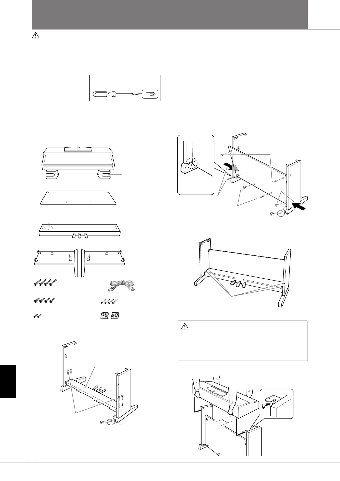
CVP-401: Keyboard Stand Assembly
CAUTION
• Be careful not to confuse parts, and be sure to install all
parts in the correct direction. Please assemble in accor-
dance with the sequence given below.
• Assembly should be carried out by at least two persons.
• Be sure to use the correct screw size, as indicated below.
Use of incorrect screws can cause damage.
• Be sure to tighten up all
screws upon completing
assembly of each unit.
•To disassemble,
reverse the assembly
sequence given below.
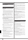
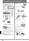
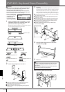
1 Open the package, take out marked “C” in the
illustration, take out the styrofoam pads, and
place the unit A on top of the pads.
Remove all parts from the box. Confirm that all parts
shown in the illustration are provided.
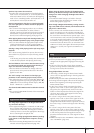
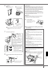
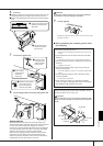
2 Attach (finger-tighten) C to D and E.
1
Untie and straighten out the bundled pedal cord. Don’t
discard the vinyl tie, you’ll need it later in step 7.
2 Align D and E with each end of C.
3 Attach D and E to C by finger-tightening the long screws
(6 ✕ 20 mm).
3 Attach B.
Depending on the model of digital piano you purchased,
the surface color of one side of the rear panel may be dif-
ferent from the other side. In this case, position the rear
panel so that the side of the surface color similar to the
side panel (left) and the side panel (right) faces the player.
1 Place the lower side of B on each foot of D and E, then attach
the upper side to D and E.
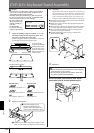
2 Attach the top of B to D and E by finger-tightening the thin
screws (4 ✕ 12mm).
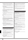
3 While pushing the lower part of D and E from outside, secure
the bottom ends of B using two tapping screws (4 ✕ 20mm).
4 Insert the other two tapping screws (4 ✕ 20mm) into the
other two screw holes to secure B.
5 Securely tighten the screws on the top of B that were
attached in Step 3-2.
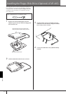
4 Securely tighten the screws on C that were
attached in Step 2-3.
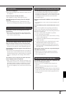
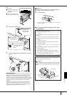
5 Mount A.
Be sure to place your hands at least 10 cm from
either end of A when positioning it.
Have a Phillips-head (+) screw-
driver ready.
A
B
C
DE
Assembly Parts AC power cord
Styrofoam pads
6 ✕ 20 mm long screws ✕ 4
6 ✕ 16 mm short screws ✕ 4
4 ✕ 12 mm thin screws ✕ 2
4 x 20 mm tapping screws ✕ 4
Cord holders ✕ 2
Bundled pedal cord inside
L
2
1
3
D
E
C
L
B
D
E
25
3
3
1
4
C
Tighten the screw.
CAUTION
• Fingers can become pinched between the unit A and
the rear or side panels, be extra careful so as not to
drop the A.
• Do not hold the keyboard in any position other than
the position shown in the illustration.
R
B
D
E
A
At least
10 cm