


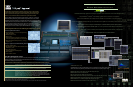


DIGITAL PRODUCTION CONSOLE DM2000
DIGITAL PRODUCTION CONSOLE DM2000
DM2000 Version 2 Specifications
GENERAL SPECIFICATIONS
Internal Signal Processing 32-bit (Accumulator 58-bit)
Sampling Frequency Internal 44.1 kHz,48 kHz,88.2 kHz,96 kHz
External Normal rate 44.1 kHz-10% to 48 kHz+6%
Double rate 88.2 kHz-10% to 96 kHz+6%
Signal Delay Less than 2.3 ms CH INPUT to STEREO OUT
(@Sampling frequency = 48 kHz)
Less than 1.2 ms CH INPUT to STEREO OUT
(@Sampling frequency = 96 kHz)
Fader motorized, touch sensitive: 100mm x 25
Total Harmonic Distortion Less than 0.05% 20Hz to 20 kHz @+14dB into 600
Ω
CH INPUT to STEREO OUT
Less than 0.01% 1 kHz @+18dB into 600
Ω
Input Gain = Min.
(@Sampling frequency = 48kHz)
Less than 0.05% 20Hz to 40 kHz @+14dB into 600
Ω
Less than 0.01% 1 kHz @+18dB into 600
Ω
(@Sampling frequency = 96kHz)
Frequency Response 0.5,-1.5dB 20Hz - 20 kHz @+4dB into 600
Ω
CH INPUT to STEREO OUT
(@Sampling frequency = 48 kHz)
0.5,-1.5dB 20Hz - 40 kHz @+4dB into 600
Ω
(@Sampling frequency = 96 kHz)
Dynamic Range 110 dB typ. DA Converter (STEREO OUT)
(maximum level to noise level)
108 dB typ. AD+DA (to STEREO OUT) @ fs=48 kHz
106 dB typ. AD+DA (to STEREO OUT) @ fs=96 kHz
Hum & Noise* -128dB Equivalent Input Noise.
(20Hz~20 kHz)
Rs =150W -92dB residual output noise. STEREO OUT
Input Gain = Max. STEREO OUT off.
Input Pad = 0dB
Input Sensitivity = -60dB -92dB (96dB S/N) STEREO OUT
STEREO fader at nominal level and
all CH INPUT faders at minimum level
-64dB (68dB S/N) STEREO OUTPUT
STEREO fader at nominal level and
one CH INPUT fader at nominal level
Maximum Voltage Gain
74dB CH INPUT (CH1-24) to STEREO OUT / OMNI (BUS) OUT
74dB CH INPUT (CH1-24) to OMNI (AUX) OUT (via pre input fader)
74dB CH INPUT (CH1-24) to CONTROL ROOM MONITOR OUT
(via STEREO bus)
* Hum & Noise are measured with a 6dB/octave filter @12.7 kHz;
equivalent to a 20 kHz filter with infinite dB/octave attenuation.
*Input Gain = Min.
*Total Harmonic Distortion is measured with a 6dB/octave filter @80kHz
Crosstalk (@1 kHz) 80dB adjacent input channels (CH1-24)
80dB input to output.
Power Requirements U/C 120V 300W 60Hz
H 230V 300W 50Hz
B 230V 300W 50Hz
Dimensions Height 257mm (including LCD)
Depth 821mm
Width 906mm
Net Weight 43kg
Operating free-air temperature range 10~35°C
Storage temperature range -20~60°C
LIBRARIES
Effect libraries (EFFECT1-8) Number of factory presets 61 (EFFECT3-8 :53)*
1
Number of user libraries 67
Compressor libraries Number of factory presets 36
Number of user libraries 92
Gate libraries Number of factory presets 4
Number of user libraries 124
EQ libraries Number of factory presets 40
Number of user libraries 160
Channel libraries Number of factory presets 2
Number of user libraries 127
GEQ libraries (EQ1-6) Number of factory presets 1
Number of user libraries 128
Surround Monitor libraries Number of factory presets 1
Number of user libraries 32
Input patch libraries Number of factory presets 1
Number of user libraries 32
Output patch libraries Number of factory presets 1
Number of user libraries 32
Bus to stereo libraries Number of factory presets 1
Number of user libraries 32
*
1
Effects 53~61 are optional Add-On Effects.These effects become fully available after installation and
authorization. Prior to installation effects 53~61 function in demo mode only.
ANALOG INPUT CHARACTERISTICS
Input Terminals
Connector in
Console
Actual Load
Impedance
For Use With
Nominal
Sensitivity
*
1
Nominal
Max. before
clip
0
-60dB
CH INPUT
A/B 1-24
26
3K Ω
10K Ω 600 Ω Lines
2TR IN ANALOG 2 [L,R]
-10dBV
(0.316 V)
-10dBV
(0.316 V)
+4dBV
(1.58V)
RCA Pin Jack
(Unbalanced)
*1.Sensitivity is the lowest level that will produce an output of +4dB (1.23V) or the nominal output level when the unit is
set to maximum gain. (all faders and level controls are maximum position.)
*2.XLR-3-31 type connectors are balanced. (1/Sleeve = GND, 2/Tip = HOT, 3/Ring = COLD)
*3.Phone jacks are balanced. (Tip = HOT, Ring = COLD, Sleeve = GND)
• In these specifications, when dB represents are specific voltage, 0dB is referenced to 0.775 Vrms.
• For 2TR IN ANALOG 2 levels, 0dBV is referenced to 1.00 Vrms.
• All 24 AD converters (CH1-24) are 24 bit linear,128times oversampling.
• +48V DC (phantom power) is supplied to CH INPUT (1-24) XLR type connectors via each individual switch.
50-600 Ω Mics
&
600 Ω Lines
-16dB
GAIN
Input Level
-70dB
(0.245mV)
-46dB
(3.88mV)
A:XLR-3-31 type
(Balanced)
*
2
-60dB
(0.775mV)
-26dB
(38.8mV)
-2dB
(616mV)
B:Phone Jack
(TRS) (Balanced) *
3
-16dB
(0.123V)
0dB
(775mV)
+24dB
(12.28V)
+10dB
(2.45V)
INSERT IN 1-24
600 Ω Lines
-6dB
(388mV)
+18dB
(6.16V)
Phone Jack
(TRS) (Balanced) *
3
+4dB
(1.23 V)
10K Ω
10K Ω
600 Ω Lines
2TR IN ANALOG 1 [L,R]
+4dB
(1.23V)
+18dB
(6.16V)
Phone Jack
(TRS) (Balanced) *
3
+4dB
(1.23 V)
ANALOG OUTPUT CHARACTERISTICS
Output Terminals
Connector in Console
Actual Source
Impedance
For Use With
Nominal
Nominal
Max. before clip
STEREO OUT [L,R]
-10dBV (0.316V) +4dBV (1.58V)
RCA Pin Jack
(Unbalanced)
+4dB (1.23 V) +18dB (6.16 V)
XLR-3-32 type
(Balanced) *
1
STUDIO
MONITOR OUT [L,R]
+4dB (1.23 V) +18dB (6.16 V)
Phone Jack
(TRS) (Balanced) *
2
C-R MONITOR OUT
LARGE [L,R]
+4dB (1.23 V) +18dB (6.16 V)
XLR-3-32 type
(Balanced) *
1
C-R MONITOR OUT
SMALL [L,R]
+4dB (1.23 V) +18dB (6.16 V)
XLR-3-32 type
(Balanced) *
1
OMNI OUT 1-8
+18dB
(default)
+4dB (1.23 V) +18dB (6.16 V)
Phone Jack
(TRS) (Balanced) *
2
+4dB
-10dB (0.245V) +4dB (1.23 V)
INSERT OUT 1-24 +4dB (1.23 V) +18dB (6.16 V)
Phone Jack
(TRS) (Balanced) *
2
PHONES
4mW 25mW
Stereo Phone Jack
(TRS) (Unbalanced) *
3
8 Ω Lines
40 Ω Lines
-
-
-
-
-
-
-
- 12mW 75mW
*1.XLR-3-32 type connectors are balanced. (1 = GND, 2 = HOT, 3 = COLD)
*2.Phone jack are balanced. (Tip = HOT, Ring = COLD, Sleeve = GND)
*3. PHONES stereo phone jack is unbalanced.
(Tip = LEFT, Ring = RIGHT, Sleeve = GND)
• STEREO OUT [L,R] , 0dBV is referenced to 1.00 Vrms.
• In these specifications, when dB represents are specific voltage,
0dB is referenced to 0.775 Vrms.
• All output (except INSERT OUT 1-24) DA converters are 24 bit,
128times oversampling.
GAIN SW
Output Level
DIGITAL INPUT CHARACTERISTICS
*1.XLR-3-31 type connectors are balanced. (1 = GND, 2 = HOT, 3 = COLD)
1
2
3
Terminal
2TR IN
DIGITAL
CASCADE IN
Format
AES/EBU
AES/EBU
IEC-60958
-
Data Length
24 bit
24 bit
24 bit
-
Level
RS422
RS422
0.5Vpp/75Ω
RS422
Connector in Console
XLR-3-31 type (Balanced) *
1
XLR-3-31 type (Balanced) *
1
RCA Pin Jack
D-SUB Half Pitch Connector 68P (Female)
DIGITAL OUTPUT CHARACTERISTICS
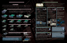
Available Mini-YGDAI card specifications
1
3
Terminal
2TR OUT
DIGITAL
CASCADE OUT
Format
-
Data Length
-
Level
RS422
RS422
RS422
Connector in Console
XLR-3-32 type (Balanced) *
4
XLR-3-32 type (Balanced) *
4
RCA Pin Jack
D-SUB Half Pitch Connector 68P (Female)
AES/EBU *
1
Professional
use
2
AES/EBU *
1
Professional
use
24 bit *
3
24 bit *
3
24 bit *
3
IEC-60958 *
2
Consumer
use
0.5Vpp/75
Ω
*1.channel status of DIGITAL OUT 1, 2
type : 2 audio channels
emphasis : NO
sampling rate : depends on the internal configuration
*2.channel status of DIGITAL OUT 3
type : 2 audio channels
category code : 2 channel PCM encoder/decoder
copy prohibit : NO
emphasis : NO
clock accuracy : Level II (1000 ppm)
sampling rate : depends on the internal configuration
*3.dither : word length 16 - 24 bit
*4.XLR-3-32 type connectors are balanced. (1 = GND, 2 = HOT, 3 = COLD)
600 Ω Lines
600 Ω Lines
10k Ω Lines
10k Ω Lines
10k Ω Lines
10k Ω Lines
600 Ω Lines
600 Ω
150 Ω
150 Ω
150 Ω
150 Ω
150 Ω
150 Ω
100 Ω
Yamaha
Maker Model Function IN OUT Format Res / Freq Connector Note
Yamaha
MY8-AT Digital I /O 8 8 ADAT 24 bit 44.1/48 kHz
Toslink x 2 Can handle 24 bit/96 kHz by double channel mode
MY8-AE Digital I /O 8 8 AES/EBU 24 bit 44.1/48 kHz
D-sub 25pin Can handle 24 bit/96 kHz by double channel mode
MY8-TD Digital I /O 8 8 TDIF 24 bit 44.1/48 kHz
D-sub 25pin Can handle 24 bit/96 kHz by double channel mode
MY16-AT Digital I /O 16 16 ADAT 24 bit 44.1/48/88.2/96 kHz
Toslink x 2 Can handle 24 bit/96 kHz by double channel mode
Check instructions for multiple use
MY16-AE Digital I /O 16 16 AES/EBU 24 bit 44.1/48/88.2/96 kHz
D-sub 25pin Can handle 24 bit/96 kHz by double channel mode
MY16-TD Digital I /O 16 16 TDIF 24 bit 44.1/48/88.2/96 kHz
D-sub 25pin Can handle 24 bit/96 kHz by double channel mode
MY8-AD24 A to D In 8 - - 24 bit 44.1/48 kHz
TRS x 8 Replacing MY8-AD (20 bit 44.1/48 kHz)
MY4-AD A to D In 4 - - 24 bit 44.1/48 kHz
XLR x 4
MY4-DA D to A Out - 4 - 20 bit 44.1/48 kHz
XLR x 4
Check instructions for multiple use
MY16-mLAN mLAN Interface 16 16 IEEE 1394 24bit, 44.1/48kHz
1394 6pin
MY8-AD96 A to D In 8 - - 24 bit 44.1/48/88.2/96 kHz
D-sub 25pin
MY8-DA96 D to A Out - 8 - 24 bit 44.1/48/88.2/96 kHz
D-sub 25pin
MY8-AE96S Digital I /O 8 8 AES/EBU 24 bit 44.1/48/88.2/96 kHz
D-sub 25pin
Sampling Rate Converter for Input, 3 cards max. with DM2000
MY16-C
CobraNet Interface
16 16 CobraNet
20/24bit, 44.1/48/88.2/96kHz
RJ45 x 4
Check instructions for multiple use
MY8-AE96 Digital I /O 8 8 AES/EBU 24 bit 44.1/48/88.2/96 kHz D-sub 25pin
Third Party
Maker Model Function IN OUT Format Res / Freq Connector Note
Waves Y96K Effect & I/O 8 8 Effect&I/O 24bit, 44.1/48/88.2/96kHz Toslink x 2
• Specifications and appearance subject to change without notice.
• All trademarks and registered trademarks are property of their respective owners.
Pro Tools
®
is a trademark of Digidesign, Avid Technology Inc.
Nuendo
®
is a trademark of Steinberg Media Technologies AG.
Adat
is a trademark of Alesis Corporation.
Tascam, TDIF, MX2424 are trademarks of Teac Corporation.
HDR24/96 is a trademark of Mackie Designs Inc.
Cobranet and Peak Audio are trademarks of Cirrus Logic, Inc.
Macintosh is a trademark of Apple Computer Inc.
Windows is a trademark of Microsoft Corporation.
Go to www.yamahaproaudio.com to check
“Guidance on the use of Mini-YGDAI cards”