


Introduzione
Introduzione a
DME Satellite
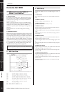
Controlli
e connettori
Connessione
a un computer
Connessione
I/O audio
Connessione a un
dispositivo esterno
Altre funzioni
Riferimenti
Riferimenti
DME8i-C/DME8o-C/DME4io-C Manuale di istruzioni
46
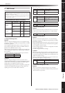
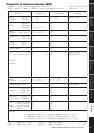
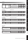
<DME4io-C>
Signal Delay
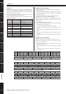
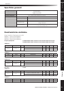
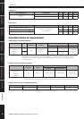
Caratteristiche di input/output
ANALOG INPUT CHARACTERISTICS
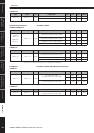
ANALOG OUTPUT CHARACTERISTICS
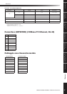
DIGITAL INPUT & OUTPUT CHARACTERISTICS
METERING POINT CONDITIONS MIN TYP MAX UNITS
INPUT 1–4
OUTPUT 1–4
PEAK red LED:ON –3 dBFs
SIGNAL green LED:ON –40 dBFs
PARAMETER CONDITIONS MIN TYP MAX UNITS
CobraNET Latency: 5.33msec
ANALOG INPUT to ANALOG
OUTPUT@96KHz
6.12 msec
CobraNET Latency: 2.67msec 3.45 msec
CobraNET Latency: 1.33msec 2.12 msec
Input Terminals GAIN Actual Load
Impedance
For Use With
Nominal
Input Level Connector
Nominal Max.before clip
<DME8i-C>
CH INPUT 1–8
<DME4io-C>
CH INPUT 1–4
–60dB
3kΩ
50–600Ω Mics &
600Ω Lines
–60dBu
(0.775mV)
–40dBu
(7.75mV)
EUROBLOCK
(5.08mm pitch)
+10dB
+10dBu
(2.45V)
+30dBu
(24.5V)
*1.In these specifications, 0dBu is referenced to 0.775 Vrms.
*2.All AD converters are 24-bit linear, 128-times oversampling (Fs=48kHz)/64-times oversampling (Fs=96kHz).
*3.+48V DC (Phantom power) is supplied to CH INPUT EUROBLOCK connectors via each individualsoftware
controlled switch.
Output Terminals Actual Source
Impedance
For Use With
Nominal
Output level Connector
Nominal Max. before clip
<DME8o-C>
CH OUTPUT 1–8
<DME4io-C>
CH OUTPUT 1–4
75Ω 600Ω Lines +4dBu (1.23 V) +24dBu(12.28V)
EUROBLOCK
(5.08mm pitch)
*1.In these specifications, 0dBu is referenced to 0.775 Vrms.
*2.All DA converters are 24-bit linear, 128-times oversampling (Fs=48kHz)/64-times oversampling (Fs=96kHz).
Terminal Format Data length Level Connector
CobraNet CobraNet 16/20/24bit 100Base-TX RJ-45x2 *1
*1.PRIMARY,SECONDARY
*2.Double Channel format and Single format are supported at 96kHz.